EasyManua.ls Logo

GE Multilin 850

GE Multilin 850
616 pages
To Next Page IconTo Next Page
To Previous Page IconTo Previous Page
Loading...
CHAPTER 4: SETPOINTS CONTROL
850 FEEDER PROTECTION SYSTEM – INSTRUCTION MANUAL 4–349
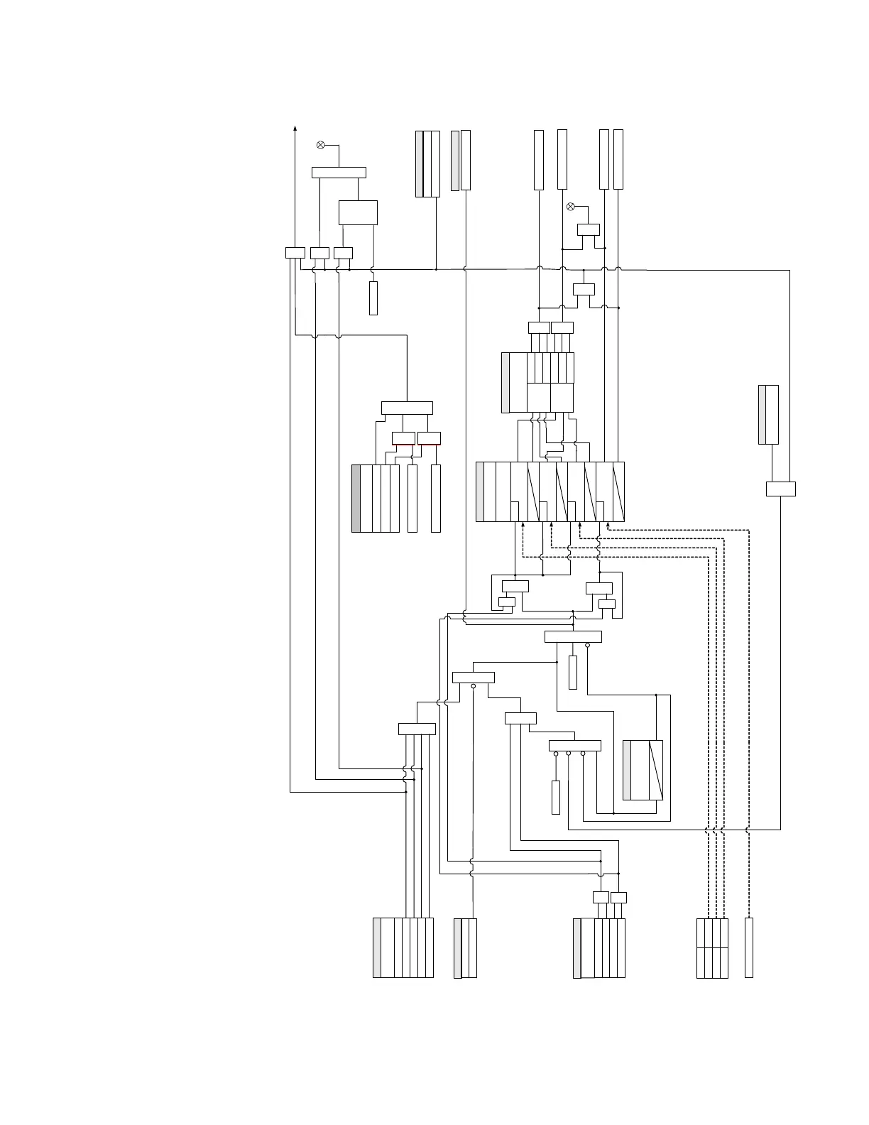
Figure 4-154: Undervoltage Restoration logic diagram
894069A3.cdr
LED: PICKUP
SETPOINTS
FUNCTION:
OR
t
PKP
0
Ph UV Restore OP
AND AND
Command
RESET
OR
LED: ALARM
SETPOINTS
BLOCK:
Off=0
AND
OR
OR
AND
AND
Command
RESET
SETPOINTS
INCOMPLETE
SEQUENCE TIME:
t
IST
0
Status Input
BKR 1 Open
Bus voltage Inputs
Line voltage input
WYE DELTA
VA (VAB) VA B
VB (VBC)
VBC
VC (VCA) VCA
Vx
SETPOINTS
UV RESTORE
MINIMUM VOLTAGE:
VA(VAB)
MINIMUM
RUN
UV RESTORE
RESTORE DELAY:
AND
t
PKP
0
VB(VBC)
MINIMUM
RUN
t
PKP
0
VC(VCA)
MINIMUM
RUN
t
PKP
0
Vx
MINIMUM
RUN
AND
SETPOINTS
UV RESTORE
PHASES FOR
OPERATION:
OPERATE:
ANY ONE
ALL
THREE
ANY TWO
PICKUP:
ANY ONE
ALL
THREE
ANY TWO
OR
Ph UV Restore PKP
Aux UV Restore OP
FlexLogic Operands
S
LATCH
Set-
Dominant
R
SETPOINTS
Phase UV 1 OP
Phase UV 2 OP
Aux UV 1 OP
Aux UV 2 OP
OR
OR
Aux UV Restore PKP
OR
OR
Disabled
Alarm
Latched Alarm
Configurable
Close
AND
INITIATION:
OR
OR
SETPOINTS
OUTPUT RELAYS (3 -7):
Do Not Operate, Operate
UV Restore Init
AND
from BKR1 Status
FlexLogic Operand
BKR 1 Closed
FlexLogic Operand
BKR 1 Closed
The Voltage Input is the same as the one used for UV element
programmed under
³
UF Restore initiation
´
to BKR1 Close Relay
Select output relay
SETPOINT
SYNCHROCHECK
SUPERVISION:
Bypass
Sync1 Close Perm
Sync1 Close Perm
From Synchrocheck 1
ANDAND
OR
Sync2 Close Perm
From Synchrocheck 2
ANDAND
Sync2 Close Perm

Table of Contents

Related product manuals