4–358 850 FEEDER PROTECTION SYSTEM – INSTRUCTION MANUAL
CONTROL CHAPTER 4: SETPOINTS
When the Incomer 1 function is selected, the TRANSFER function operates according
to the Transfer Scheme Incomer Breaker 1 logic (see INCOMER BREAKER 1 Logic
Diagram below) and TRANSFER setting.
When the Incomer 2 function is selected, the TRANSFER function operates according
to the Transfer Scheme Incomer Breaker 2 logic (see INCOMER BREAKER 2 Logic
Diagram below) and TRANSFER setting.
When the Bus Tie function is selected, the TRANSFER function operates according to
the Transfer Scheme Bus Tie Breaker logic (see BUS TIE BREAKER Logic Diagram
below) and Transfer Bus Tie setting.
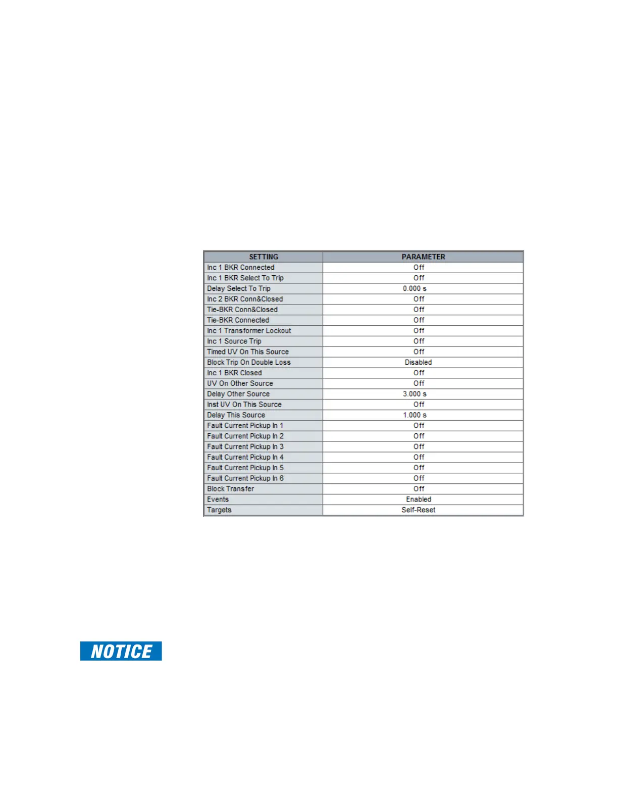
850 RELAY – INCOMER 1
When the INCOMER 1 function is selected the following display is available:
INC 1 BKR CONNECTED
Range: Off, Any FlexLogic operand
Default: Off
The setpoint selects the FlexLogic operand, digital input, virtual input or remote input
used to inhibit transfer if Incomer breaker 1 cannot be used to pass current from the
source to the load (for example when the breaker is in rack-out or test position). This
setpoint also provides the condition for “Selected to Trip” breaker logic, FlexLogic
operand INC1 CB CON & CLSD required for Incomer 2 Circuit Breaker transfer logic, Bus
Tie Circuit Breaker transfer logic, and for blocking #2 close relay.
FAST PATH:
For non-draw-out breakers without associated disconnect switches, this setpoint must be
set as ON.