CHAPTER 4: SETPOINTS CONTROL
850 FEEDER PROTECTION SYSTEM – INSTRUCTION MANUAL 4–371
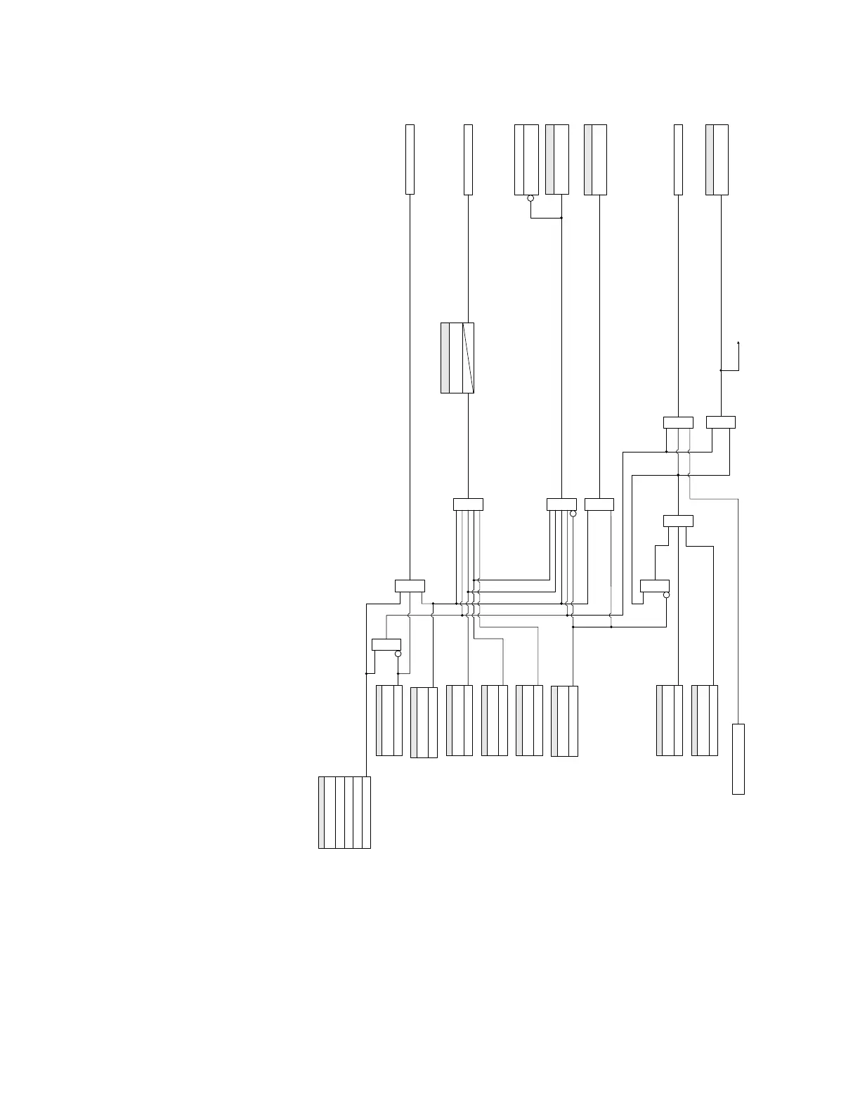
Figure 4-159: Transfer Scheme - Bus Tie Breaker logic diagram
After the lost source has been re-established, there are three methods to restore the
system to normal configuration. Two methods are manual and one is automatic:
• Manual Method 1 - when the sources cannot be synchronized: The Bus Tie Breaker
must be manually opened before the open incomer can be manually closed. In this
procedure the incomer is allowed to close only if the incoming source (Line VT) voltage
is above a live threshold and the load (Bus VT) voltage is below a dead threshold value
(setpoints for voltage check - dead sources associated with the Synchrocheck
function must be set).
892761A2.cdr
SETPOINT
TRANSFER FUNCTION:
Disabled
Incomer 1
AND
Incomer 2
Tie
AND
FlexLogic Operand
Tie-BKR Trfer Rdy
SETPOINT
INC1 BKR CONN & CLSD:
Off = 0
SETPOINT
CLS TIE-BKR FROM INC1:
Off = 0
SETPOINT
TIE BKR SLCTD TO TRIP:
Off = 0
SETPOINT
BLOCK TRANSFER:
Off = 0
FlexLogic Operand
Tie-BKR Con&Clsd:
AND
BLOCK #2 (CLOSE RLY)
SETPOINT
DELAY SELECT TO TRIP:
Tdstt
AND
0
AND
SETPOINT
INC2 BKR CONN & CLSD:
Off = 0
TRIP #1 (TRIP RLY)
SETPOINT
CLS TIE-BKR FROM INC2:
Off = 0
OR
AND
AND
SYNC 1 DEAD SRC OK
CLOSE #2 (CLOSE RLY)
Transfer Not Ready
Target Message
From Synchrocheck
Transfer Initiated
(to Synchrocheck and Event Recorder)
SETPOINT
Tie-BKR CONNECTED:
Off = 0
SETPOINT
Tie-BKR CLOSED:
Off = 0
FlexLogic Operand
Transfer Initiated
AND