EasyManua.ls Logo

GE Multilin 850

GE Multilin 850
616 pages
To Next Page IconTo Next Page
To Previous Page IconTo Previous Page
Loading...
4–400 850 FEEDER PROTECTION SYSTEM – INSTRUCTION MANUAL
CONTROL CHAPTER 4: SETPOINTS
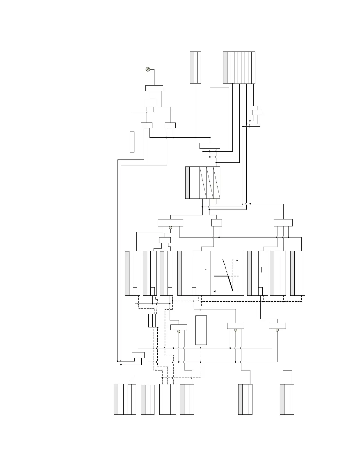
Figure 4-169: CT Supervision logic diagram
894179A1.cdr
SETPOINTS
OR
AND
SETPOINT
Symmetry Check:
Disabled = 0
LED: ALARM
RESET
Command
AND
S
R
LATCH
Seq. 3I0 PKP:
Calculate
AND
SETPOINT
BLOCK:
Off = 0
3I
0
> PKP
RUN
Seq. 3V0 PKP:
3V
0
> PKP
RUN
Seq. IG PKP:
I
G
> PKP
RUN
SETPOINTS
OR
3I0
3V0
SETPOINT
Differential Check:
Disabled = 0
SETPOINT
Sequence Check:
Disabled = 0
SETPOINTS
Diff. Current PKP:
Diff. Slope:
Diff. IG Polarity:
I
CTSdiff
= | - |
I
CTSdiff
> PKP (if Slope=0)
I
CTSdiff
> (Slope*I
max
) + PKP
(if Slope 0)
RUN
I
CTSdiff
I
max
Select
I
max
= max(|¯I
a
|,|
b
|,|
c
|)
I
min
= min(|
a
|,|
b
|,|
c
|)
AND
SETPOINTS
Sym. Quotient PKP:
Q = I
min
I
max
Q < PKP
RUN
SETPOINTS
Sym. Min Current:
I
max
> Sym. Min Current
t
Pickup Delay:
(3 Individual Timers with
same delay setting)
SETPOINT
pkp
20 ms
OR
CTS Alarm OP
FlexLogic Operands
CTS Seq Check OP
CTS Diff Check OP
CTS Sym Check OP
CTS Seq Check PKP
CTS Diff Check PKP
CTS Sym Check PKP
CTS Alarm PKP
OR
SETPOINTS
Max Current Supervision:
I
max
< Max Current Supervision
SETPOINTS
OPERATE BLOCK
Slope
I
Lmax
PKP
SETPOINT
Function:
Disabled
Latched Alarm
t
pkp
20 ms
t
pkp
20 ms
Alarm
Measured: I
A
, I
B
, I
C
Measured: V
A
, V
B
, V
C
OR
AND AND
AND
AND
OUTPUT RELAYS
SETPOINTS
Do Not Operate, Operate
Measured: I
G
¯
I
0
3
G
¯I
=
¯I
¯I¯I¯I

Table of Contents

Related product manuals