CHAPTER 4: SETPOINTS FLEXLOGIC
850 FEEDER PROTECTION SYSTEM – INSTRUCTION MANUAL 4–413
The characteristics of the logic gates are tabulated below, and the operators available in
FlexLogic™ are listed in the FlexLogic™ operators table.
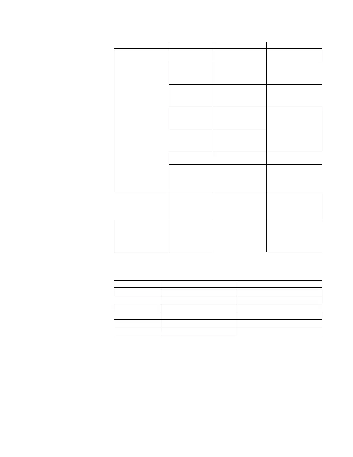
Table 4-41: FlexLogic Gate Characteristics
FLEXLOGIC RULES
When forming a FlexLogic™ equation, the sequence in the linear array of parameters must
follow these general rules:
1. Operands must precede the operator which uses the operands as inputs.
2. Operators have only one output. The output of an operator must be used to create a
Virtual Output if it is to be used as an input to two or more operators.
3. Assigning the output of an operator to a Virtual Output terminates the equation.
4. A timer operator (for example, "TIMER 1") or Virtual Output assignment (for example,
" = Virt Op 1") may only be used once. If this rule is broken, a syntax error will be
declared.
Logic gate NOT Logical NOT Operates on the previous
parameter.
OR(2)↓ OR(16) 2 input OR gate↓ 16
input OR gate
Operates on the 2
previous parameters.
↓Operates on the 16
previous parameters.
AND(2)↓ AND(16) 2 input AND gate↓ 16
input AND gate
Operates on the 2
previous parameters.
↓Operates on the 16
previous parameters.
NOR(2)↓ NOR(16) 2 input NOR gate↓ 16
input NOR gate
Operates on the 2
previous parameters.
↓Operates on the 16
previous parameters.
NAND(2)↓ NAND(16) 2 input NAND gate↓ 16
input NAND gate
Operates on the 2
previous parameters.
↓Operates on the 16
previous parameters.
XOR(2) 2 input Exclusive OR gate Operates on the 2
previous parameters.
LATCH (S,R) Latch (set, reset): reset-
dominant
The parameter preceding
LATCH(S,R) is the reset
input. The parameter
preceding the reset input
is the set input.
Timer TIMER 1↓ TIMER 32 Timer set with
FlexLogic™ timer 1
settings. ↓ Timer set with
FlexLogic™ timer 32
settings.
The timer is started by
the preceding parameter.
The output of the timer is
TIMER #.
Assign virtual output = Virt Op 1↓ = Virt
Op 32
Assigns previous
FlexLogic™ operand to
virtual output 1.↓ Assigns
previous FlexLogic™
operand to virtual output
96.
The virtual output is set
by the preceding
parameter
GATES NUMBER OF INPUTS OUTPUT IS ‘1’ (= ON) IF...
NOT 1 input is ‘0’
OR 2 to 16 any input is ‘1’
AND 2 to 16 all inputs are ‘1’
NOR 2 to 16 all inputs are ‘0’
NAND 2 to 16 any input is ‘0’
XOR 2 only one input is ‘1’
TYPE SYNTAX DESCRIPTION NOTES

 Loading...


