SecoGear Medium-voltage Switchgear Application and Technical Guide DET-882
SecoGear Switchgear Concepts and Basic Configurations
2 ©2017 General Electric All Rights Reserved
• SecoGear utilizes modular construction resulting in one
basic vertical section size, simplifying system planning
and increasing installation savings
• SecoGear features four-high auxiliary arrangements,
providing additional flexibility and use of floor space
• SecoGear allows for intermixing auxiliary and a breaker
compartment in the same vertical section
Certain elements in the switchgear application procedure
are affected by these fundamental design features. Cubicle
stacking, cabling direction, and VT & CPT compartment
considerations are key when translating the one-line
diagram into a valid arrangement of switchgear cubicles,
auxiliary rollouts, and bus connections in a lineup. These
application considerations are necessary as a result of the
equipment design. A brief illustration of SecoGear
switchgear design concepts is provided to assist in
understanding.
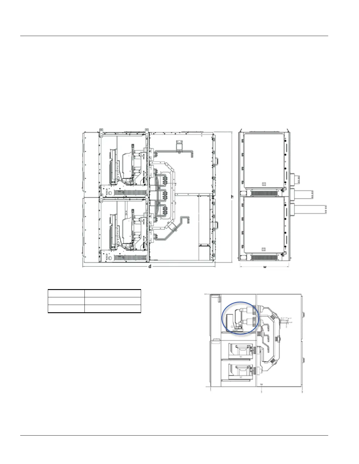
Figure 1-2: Section Contents
Table 1-1: Typical Dimensions for Indoor Construction
95 in [2413 mm]
36 in [914 mm]
95.05 in [2414 mm]
Breakers and auxiliary devices can be accommodated in
the upper and lower compartments, as shown in Figure 1-3
and Figure 1-4, in a variety of configurations.
Figure 1-3: Typical One-High Breaker
Compartment
B = Circuit Breaker
Compartment
C = Cable
Compartment
D
B
B
C
C