SecoGear Medium-voltage Switchgear Application and Technical Guide DET-882
Circuit Breaker Selection
12 ©2017 General Electric All Rights Reserved
tie breakers. In normal operating mode, each bus is served
by its own source through normally closed main breakers,
with the bus tie breaker open. If an outage occurs on one
of the incoming supplies, the incoming breaker connected
to that supply is opened, and then the bus is re-energized
by closing the bus tie breaker to transfer the dead bus to
the live (alternate) source.
To protect against damage to motors connected to the
dead bus, the bus tie breaker is typically not allowed to
close until the residual voltage on the effected bus has
decayed to a safe level. After the lost source has been
reestablished, the scheme provides two methods (auto and
manual) to restore the system to normal configuration.
If the sources cannot be synchronized, the bus tie breaker
must be manually opened before the open incomer can be
manually closed. In this procedure, the incomer will be
allowed to close only if the incoming source (line VT)
voltage is above a “live” threshold and the load (bus VT)
voltage is below a “dead” threshold value.
If the sources are synchronized, it is possible to manually
close the open incomer with synch check supervision to
parallel all three breakers. The scheme will then
automatically open a breaker which had been previously
selected to trip if all breakers become closed, in this
instance the bus tie breaker. Note that if momentary
paralleling is utilized, the equipment and breakers must be
rated for the total available fault current from the
combined sources.
The detection of an undervoltage event and the resulting
transfer logic can be accomplished using either discrete
protective relays, auxiliary relays and timers, or with a PLC
and programming, or by using the various protective relay
and logic features contained in today’s multifunction
relays, such as GE Multilin SR850. In addition to a protective
relay required for each of the three circuit breakers (both
mains and the tie), it is required to connect one contact
from a three-position switch to each breaker. This switch
(device 43/10) is used to select the breaker that will trip
after all breakers are closed. It is generally recommended
that a two-position switch (device 43/83) with three
contacts, be connected to each relay as an “Auto-Off”
transfer scheme selector.
Because a relay is required for each the three circuit
breakers, it allows bus-splitting. This operation is
accomplished by setting the time overcurrent elements in
the relay on the bus tie breaker to trip faster than the
incomers, opening the bus tie before an incomer when
operating from only one source.
Capacitor Switching
Capacitor banks are generally applied on both utility and
industrial power systems to improve voltage regulation
and system stability. SecoVac VB2+ circuit breakers
properly equipped are applicable as circuit breakers for
small shunt-capacitor-bank switching applications.
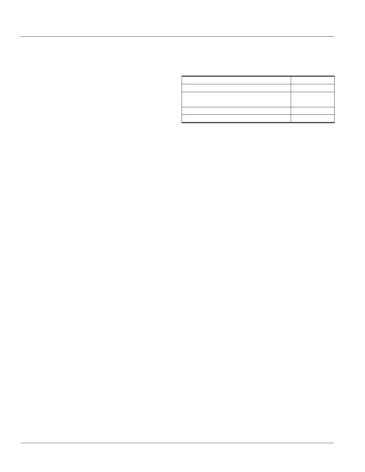
Table 2-2: SecoVac Breaker
Capacitor Switching Capabilities
Rated Short-circuit Current
Single Bank Rated Capacitor Breaking
Current (1200 A Breaker)
250 A
C2
60 Hz
SERVICE CONDITIONS
ANSI defines specific service conditions as “usual” or
“unusual” for the operation of metal-clad switchgear;
based on factors such as altitude, temperature, humidity
and a variety of others, like presence of atmospheric
contaminants storage conditions and tamper resistance.
ANSI C37.04 specifies service conditions for circuit breakers
and ANSI C37.20.2 for metal-clad switchgear.
Usual Service Conditions
SecoVac VB2+ circuit breakers and the complete SecoGear
switchgear assembly are designed for usual service
conditions at their standard nameplate ratings;
• Ambient temperature range: maximum 40 °C [104 °F]
and minimum -30°C [-22 °F]
• Altitude: maximum 1000 m [3300 feet]
Unusual Service Conditions
Abnormal Temperature
For special applications with unusual service conditions
such as ambient temperature outside normal range (-30 °C
[-22 °F] to 40 °C [104 °F], consult ANSI C37.20.2 for derating
values applicable. Refer special or abnormal applications to
GE for evaluation.
Temperature Rise
The temperature of the buses and bolted connections in
any switchgear assembly must not exceed 65 °C [149 °F]
when operating under full load current, and the total hot
spot must not exceed 105 °C [221 °F], as stated in ANSI
C37.20.2. Connections to insulated cables must not exceed
a 45 °C [113 °F] temperature rise, and an 85 °C [185 °F] hot
spot temperature when operated at rated continuous
current in rms amperes at rated frequency.
High Altitude
There are two characteristics to take into consideration
when designing medium voltage metal-clad switchgear at
altitudes above 1000 meters [3300 ft]: continuous current
rating and dielectric withstand capability. Both of them use