SecoGear Medium-voltage Switchgear Application and Technical Guide DET-882
Control Power Equipment
24 ©2017 General Electric All Rights Reserved
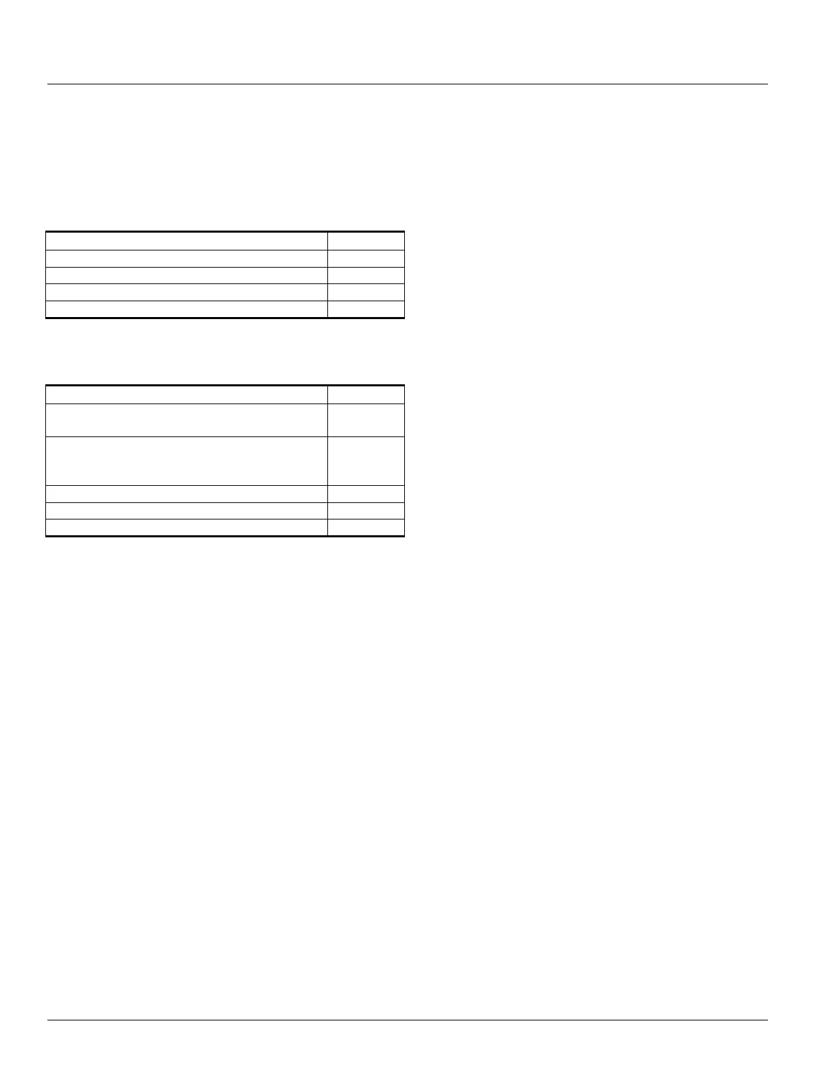
GUIDE TO ESTIMATING HEAT LOSS
When operating at nameplate rating, SecoGear Metal-clad
switchgear heat losses per section should be estimated by
adding the individual components of heat loss as shown in
Table 3-10 and then add each item from Table 3-11 as
they apply in the switchgear line-up.
Table 3-10: Heat Loss per Breaker
Breaker and Bus Work Per Vertical Section
2-1200 A breakers, stacked
1-1200 A & 1-2000 A breaker, stacked
To the above figures add the following as they apply to the
lineup:
Table 3-11: Heat Loss per Section
SecoGear Sections or Component
Each vertical section with simple (typical)
relaying and control
Each vertical section with complex relaying
and control (differential relaying, backup
Each CPT rollout up to 15 kVA
Equipment heaters if supplied (per section)
The following formulas convert Watts to BTUs:
• BTUs per minute = Watts x 0.05688
• BTUs per hour = Watts x 3.4128