SecoGear Medium-voltage Switchgear Application and Technical Guide DET-882
SecoGear Switchgear Concepts and Basic Configurations
6 ©2017 General Electric All Rights Reserved
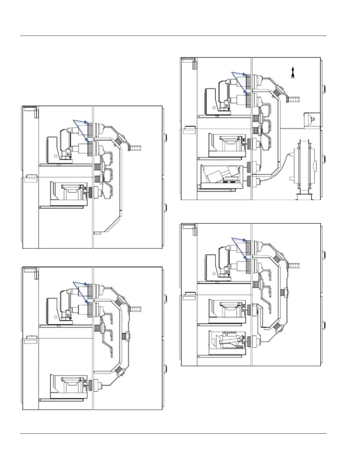
Two-High Breaker and Auxiliary Stacking
SecoGear allows stacking of various modules or
compartments into a vertical section. Typical equipment
section views in Figure 1-11 through Figure 1-26 illustrate
how upper and lower units can be combined with the
associated power connections.
Figure 1-11: Breaker in Compartment A, Bus-connected
VTs in Compartment B
Figure 1-12: Breaker in Compartment A, Line-connected
VTs in Compartment B
Figure 1-13: Breaker in Compartment A, Bus-connected
VTs and CPT Fuse Rollout in Compartment B
* Cabling to the breaker must enter or exit above.
Figure 1-14: Breaker in Compartment A, Line-connected
CPT and VT Rollouts in Compartment B
A
B
A
B
A
B
A
B