EasyManuals Logo

GE SecoGear Application Guide

GE SecoGear
76 pages
To Next Page IconTo Next Page
To Previous Page IconTo Previous Page
Page #73 background imageLoading...
Page #73 background image
DET-882 SecoGear Medium-voltage Switchgear Application and Technical Guide
Standard SecoGear Construction, Features, and Installation
©2017 General Electric All Rights Reserved 65
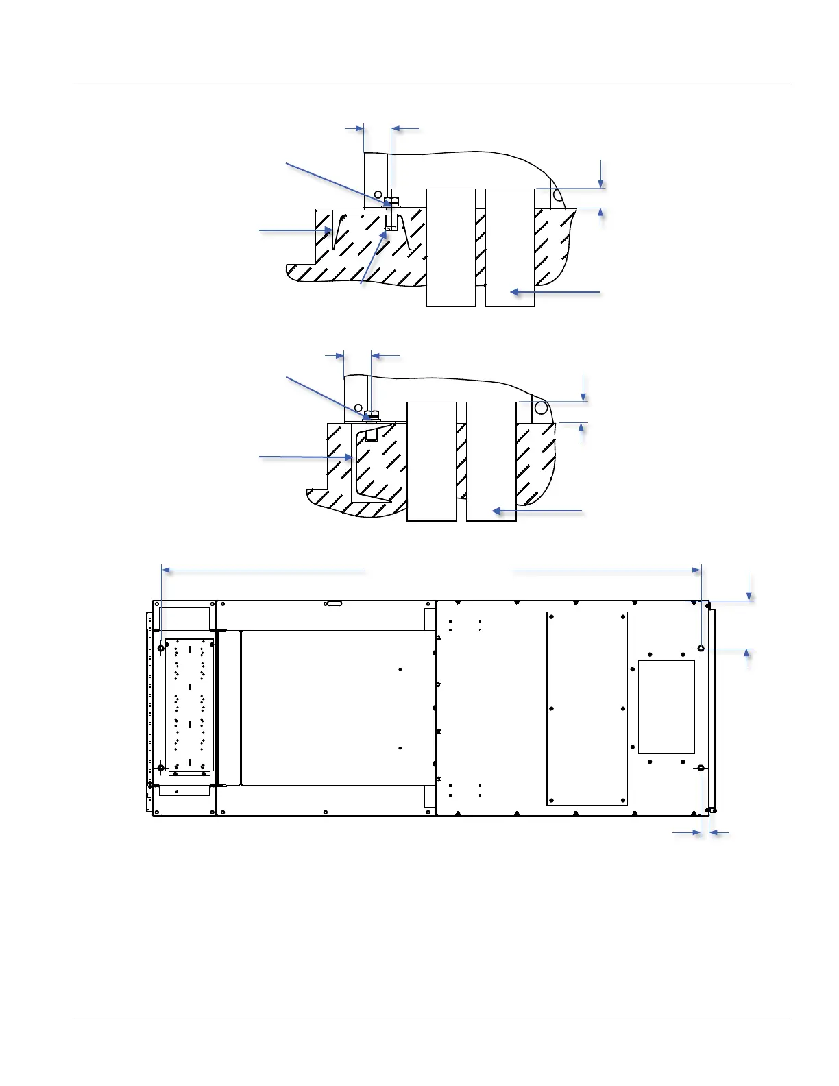
Figure 6-31: SecoGear Primary Indoor Anchoring Method
Figure 6-32: SecoGear Alternate Indoor Anchoring Method
Figure 6-33: Installation Top View
Conduit Leads
Embedded Channel
C5 x 6.7# min.
Clearance Space
2Ø 18.0 mm [0.709 in] Holes
for M12 [0.5 in] Anchor
Bolts, Front & Rear
35.05 mm [1.38 in]
25.4 mm [1.0 in] max.
Conduit Leads
Embedded Channel
C5 x 6.7# min.
2Ø 18.0 mm [0.709 in] Holes
for M12 [0.5 in] Anchor
Bolts, Front & Rear
35.05 mm [1.38 in]
25.4 mm [1.0 in] max.
Front Door
914.4 mm [36 in]
(required min. space for
rear hinged covers)
203.2 mm
[8.0 in]
2290.06 mm [90.16 in]
35.05 mm [1.38 in]

Table of Contents

Other manuals for GE SecoGear

Questions and Answers:

Question and Answer IconNeed help?

Do you have a question about the GE SecoGear and is the answer not in the manual?

GE SecoGear Specifications

General IconGeneral
BrandGE
ModelSecoGear
CategorySwitch
LanguageEnglish

Related product manuals