EasyManua.ls Logo

GE SecoGear - Standard Tie Breaker and Auxiliary Configurations; Figure 5-12: Tie Breaker and Aux Tie Stack; Figure 5-13: Bus Vts on each Side of Tie Breaker; Figure 5-14: Feeder Breakers in Upper Compartment

GE SecoGear
76 pages
To Next Page IconTo Next Page
To Previous Page IconTo Previous Page
Loading...
DET-882 SecoGear Medium-voltage Switchgear Application and Technical Guide
SecoGear Switchgear Applications
©2017 General Electric All Rights Reserved 53
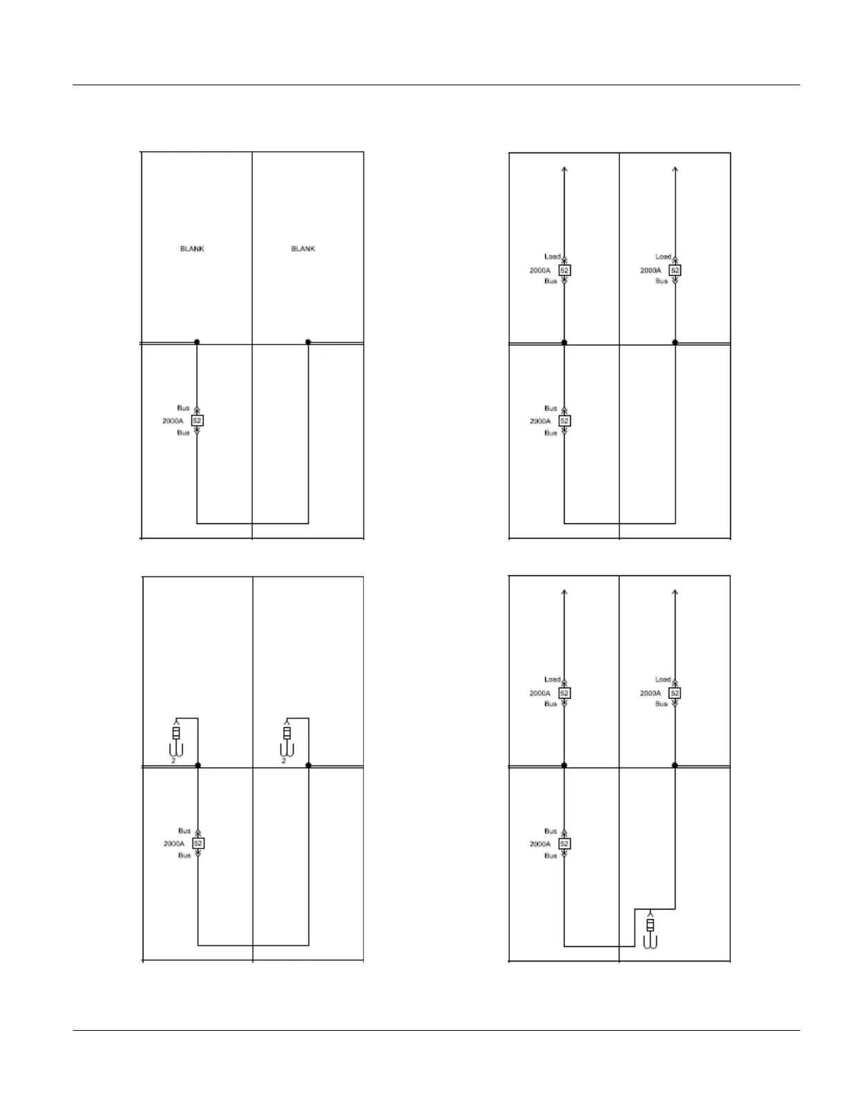
STANDARD TIE BREAKER AND AUXILIARY CONFIGURATIONS
Figure 5-12: Tie Breaker and Aux Tie Stack
Figure 5-13: Bus VTs on Each Side of Tie Breaker
Figure 5-14: Feeder Breakers in Upper Compartment
Figure 5-15: Bus VT in the Aux Tie Compartment

Table of Contents

Other manuals for GE SecoGear

Related product manuals