SecoGear Medium-voltage Switchgear Application and Technical Guide DET-882
Circuit Breaker Selection
16 ©2017 General Electric All Rights Reserved
TYPICAL BREAKER DEVICE INTERNALS
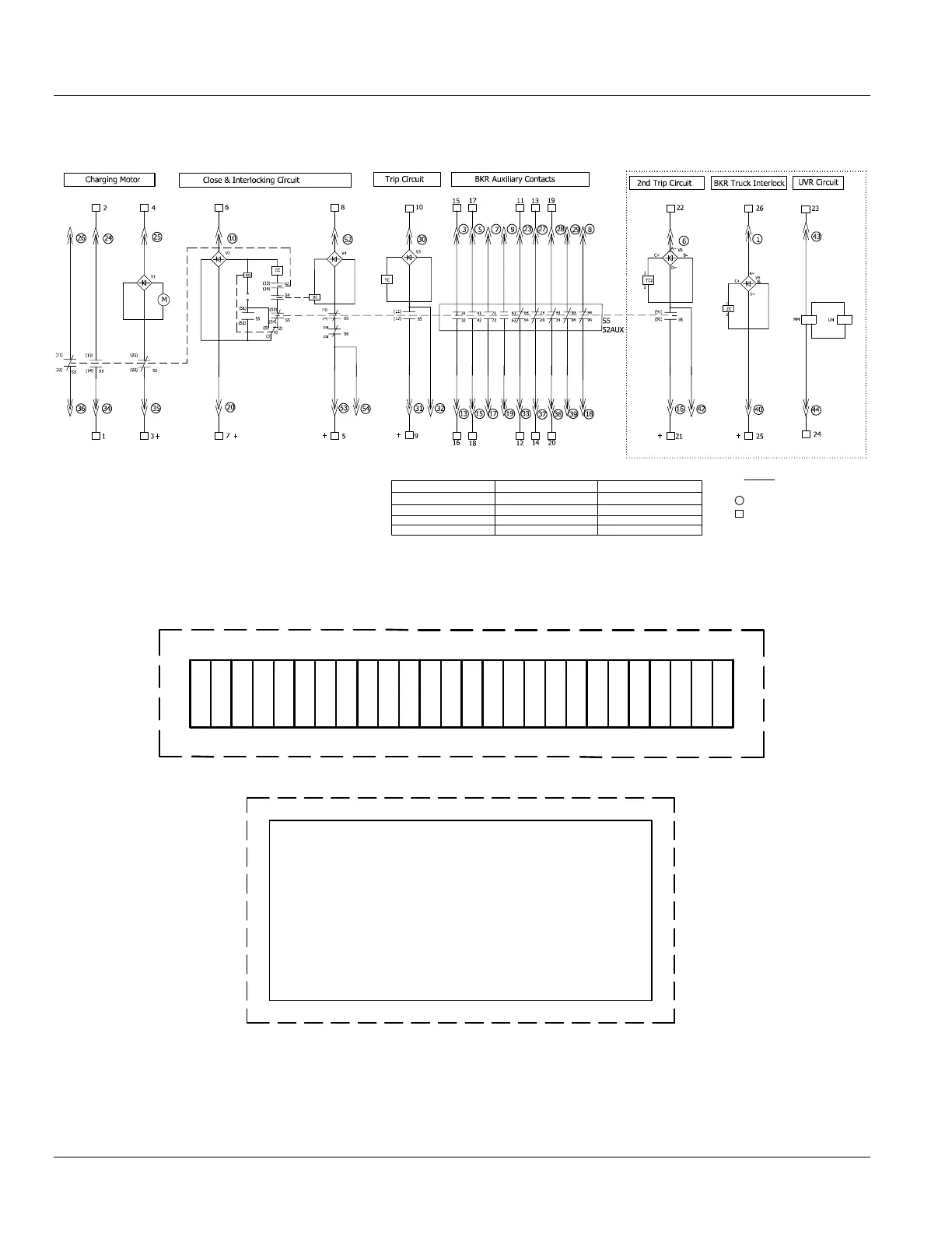
Figure 2-5: System Wiring Diagram
Notes:
1. This wiring diagram depicts a breaker that is open, racked to test position, with spring in discharge state.
2. Optional features are shown in the dotted box.
Figure 2-6: Terminal Block Located in Switchgear
Figure 2-7: Secondary Disconnect
Anti-pumping relay
Auxiliary switch
Close Block Contact
Energy storing travel switch
S1~S3:
S5/52AUX:
M:
Spring Charge Motor
K0:
TC:
CC:
Closing coil
Trip coil
BC:
MM UM:
Close Block Solenoid
UVR coil (optional)
Rectifier
V1~V6:
ZC:
BKR Lock Solenoid (Optional)
Limit switch for trip free
TC2:
2nd Trip coil (optional)
xx
xx
(xx)
Switchgear Terminal block Number.
Breaker Secondary Pin Number.
Auxiliary Contact Number.
Key Note
21 3 4 5 6 7 8 9
10
11 12 13 14 15 16 17 18 19 20 21 22 23 24 25 26
1 2 3
4
5 6 7
8
9
10 11 12 13 14 15
16
17 18 19
20
21
22
23
24
25 26 27
28
29 30 31
32 33 34 35 36 37
38 39 40
585755 5653 54
51 5249 50
47
48
45
46
43
44
42
41