SecoGear Medium-voltage Switchgear Application and Technical Guide DET-882
Standard SecoGear Construction, Features, and Installation
60 ©2017 General Electric All Rights Reserved
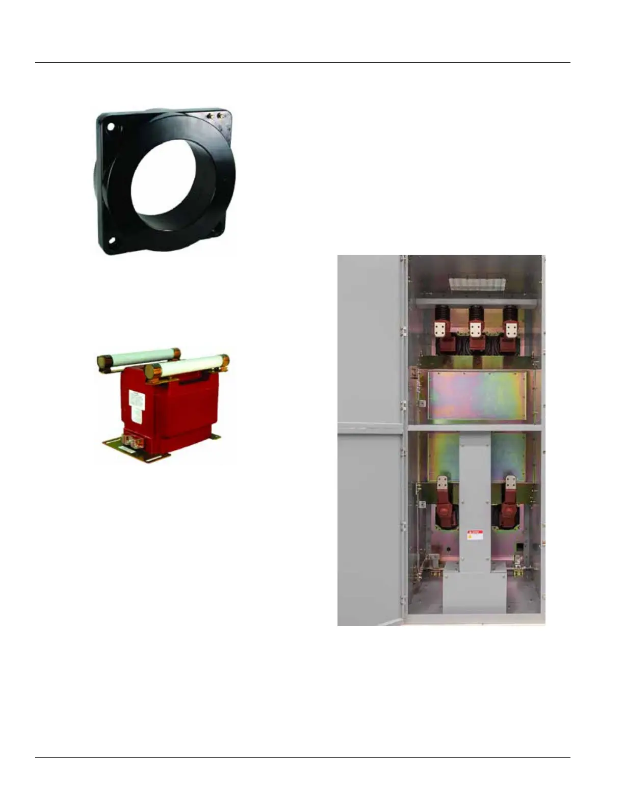
Figure 6-18: Typical Ring-Type CTs
Mounted in SecoGear Breaker Cell
Voltage transformers and their associated fuses are
mounted on rollout trays. Standard voltage transformers
are GE/ITI type PTG-5, mounted three per tray for wye
connection transformers and two per tray for open-delta
connected transformers.
Figure 6-19: Typical Indoor Voltage Transformer
Control power transformers can be mounted in a rollout
tray up to a maximum of 15 kVA. For applications that
require the use of a CPT larger than 15 kVA, SecoGear can
accommodate fix-mounted CPTs up to 45 kVA single phase
and 45 kVA three phase. The drawer will accommodate as
many as three Class C fuses. A secondary molded case
circuit breaker is key interlocked with the drawout fuse
trays, to prevent withdrawing the fuses while under load.
Wiring
For standard applications, a No. 14, tinned-copper wire,
rated 600 V will be used for secondary control wiring. Some
applications or circuits might require a larger wire.
Secondary control wires can pass around primary
compartments through enclosed grounded metal troughs.
Standard wire ends are furnished with crimp type,
uninsulated spade terminals and sleeve type wire markers.
Power Termination Compartment
Cable termination compartments for incoming and load
cables are located at the rear of the equipment and are
accessible through the rear covers. Each cable termination
pad can accommodate two 750 KCMIL cables per phase as
standard.
As required, the power-termination compartment may be
used for mounting stationary CPTs, wound-primary CTs,
ground-sensor CTs, GE standard surge suppressors, surge
arrestors, and other auxiliary devices.
Load cables for two-high breaker arrangements are
isolated by a cable trough design. This provides the
required isolation of each set of cables. Identification of
cabling direction is critical to engineering during
construction phase. See Figure 6-20 and Figure 6-21.
Figure 6-20: Rear View of Two high Compartment
Showing Cable Trough