EasyManua.ls Logo

GE SecoGear - Figure 1-23: Breaker in Compartment a - Cabling Above, Bus Entry in Compartment B - Cabling below; Figure 1-24: Breaker in Compartment A, Bus-Connected Vts and Line-Connected Fuse Rollout in Compartment B; Figure 1-25: Bus-Connected Vts in Compartment A, Bus Tie Breaker in Compartment B; Figure 1-26: Bus-Connected Vts in Compartment A, Aux Tie in Compartment B

GE SecoGear
76 pages
Print Icon
To Next Page IconTo Next Page
To Previous Page IconTo Previous Page
Loading...
DET-882 SecoGear Medium-voltage Switchgear Application and Technical Guide
SecoGear Switchgear Concepts and Basic Configurations
©2017 General Electric All Rights Reserved 9
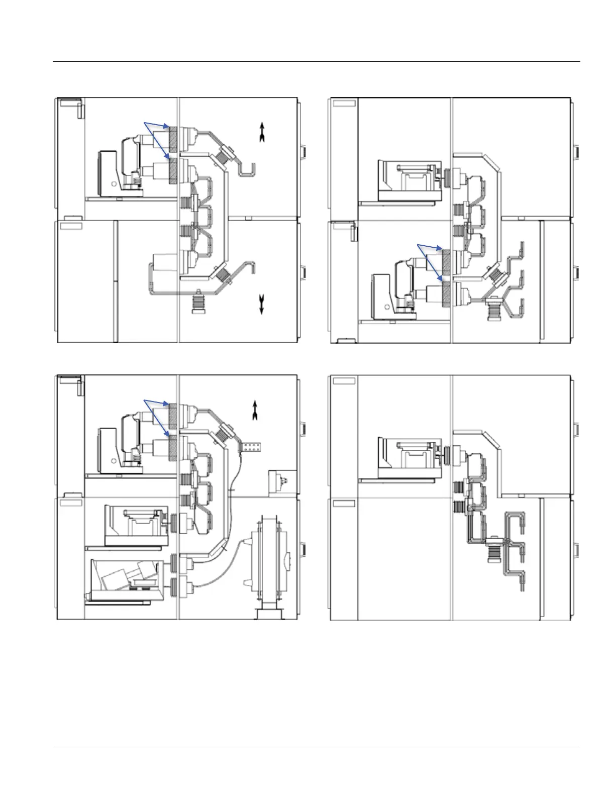
Figure 1-23: Breaker in Compartment ACabling Above,
Bus Entry in Compartment BCabling Below
Figure 1-24: Breaker in Compartment A, Bus-connected
VTs and Line-connected Fuse Rollout in Compartment B
Figure 1-25: Bus-connected VTs in Compartment A, Bus
Tie Breaker in Compartment B
Figure 1-26: Bus-connected VTs in Compartment A, Aux
Tie in Compartment B
Breaker
A
B
CTs
Breaker*
Fuse Rollout
A
B
CTs
VT
Breaker
A
B
CTs
VT
A
B
VT

Table of Contents

Other manuals for GE SecoGear

Related product manuals