SecoGear Medium-voltage Switchgear Application and Technical Guide DET-882
SecoGear Switchgear Applications
54 ©2017 General Electric All Rights Reserved
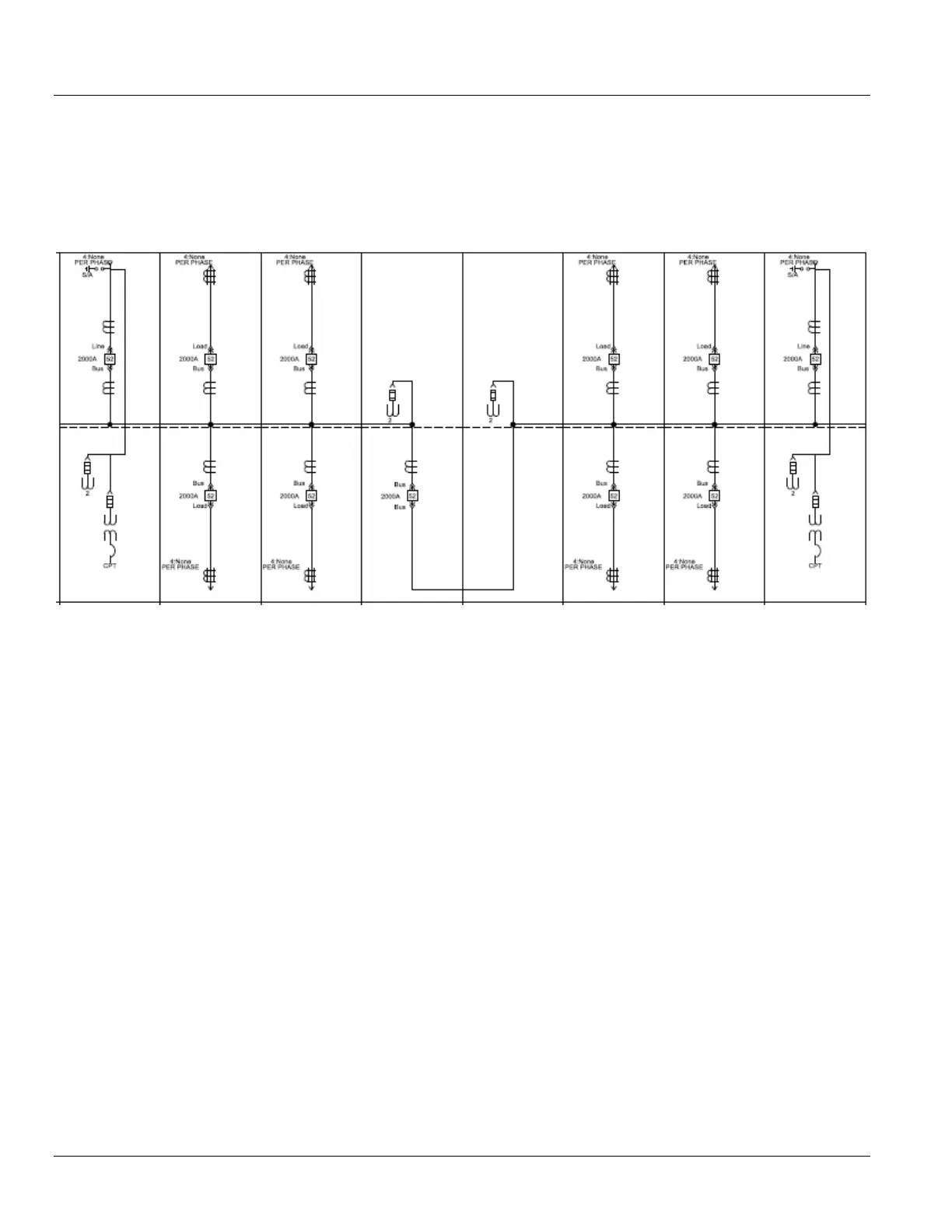
The lineup in Figure 5-16 shows VTs and CPTs line connected
for each incoming source. Included in this arrangement are
dedicated bus VTs connected on each side of the tie breaker.
Each feeder breaker is shown with relaying CTs and GSCTs.
The main breakers are shown with two sets of CTs and
incoming surge arrestors. Incoming source connections are
shown entering from above.
The main breakers can also be arranged on the ends of this
main-tie-main arrangement, allowing for more options when
either hot or cold sequence. Utility metering is required.
Figure 5-16: Typical Main-Tie-Main Example with Eight Feeder Breakers

 Loading...


