SecoGear Medium-voltage Switchgear Application and Technical Guide DET-882
SecoGear Switchgear Applications
42 ©2017 General Electric All Rights Reserved
Watts, Vars, PF and demand functions (such as GE 850 &
F650).
• Test Blocks: For circuits that require the provisions for
insertion of portable recording meters or other similar
devices, add current and voltage test block. Basic test
block is wired to maintain the circuit when the test plug is
removed.
• Indicating Lamp: Additional indicating lamps can be
provided, such as for circuits requiring a circuit breaker
disagreement or spring-charged indication function.
Control
• Control Voltage: Available control voltages are 48 Vdc,
125 Vdc, 250 Vdc, 120 Vac and 240 Vac. For AC control, if
a reliable 120 Vac/240 Vac source is not available at the
site, then include a control power transformer connected
to each incoming line in each lineup, plus an auto-
charged, capacitor-trip device for each circuit breaker
and each lockout relay (86) in the lineup. For dual sources
with normally open-tie circuit breaker and AC control,
add CPT throwover contactor.
• Remote Control: For circuit breakers controlled from a
remote location, choose the remote control scheme for
those listed in Table 4-1. From this table, Scheme C is
recommended, since it provides maximum operating
flexibility. It requires the use of a breaker position switch
in conjunction with the breaker control switch to provide
the permissive function. With Scheme C, remote close
and trip is possible only with the breaker in the “connect”
position; local close with the breaker in the
“test/disconnect” position; and local trip with the breaker
in the “connect” or “test/disconnect” position.
If several optional devices are added to an incoming line
section, there may not be sufficient space to mount them
all. In this case, specify excess relays to be mounted on
the tie-breaker vertical section or on an adjacent
auxiliary compartment.
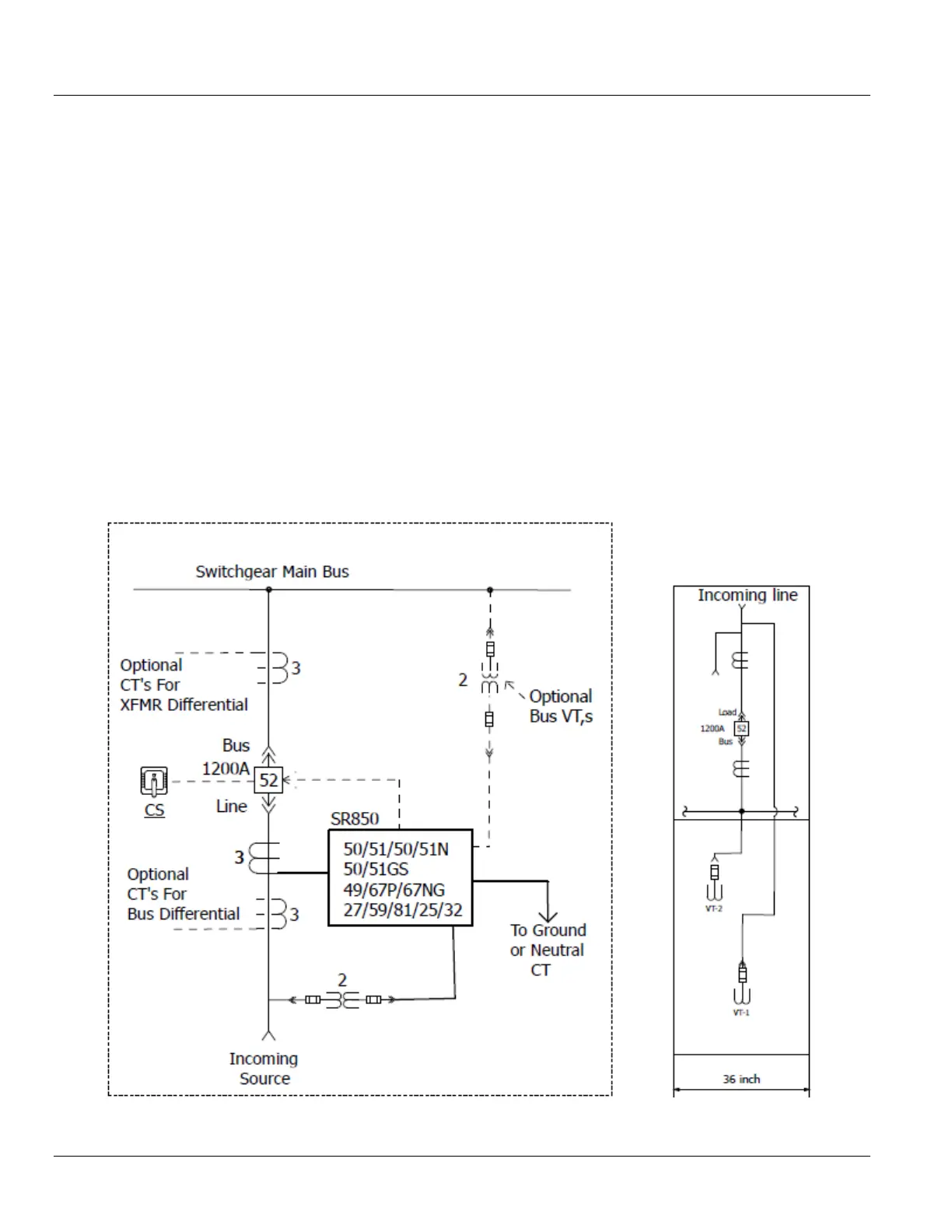
Figure 5-3: Single-source Incoming Line