GE_UPS_OPM_TLE_SCE_M60_M80_1GB_V020.docx
User Manual TLE Series 600 & 800 CE S1
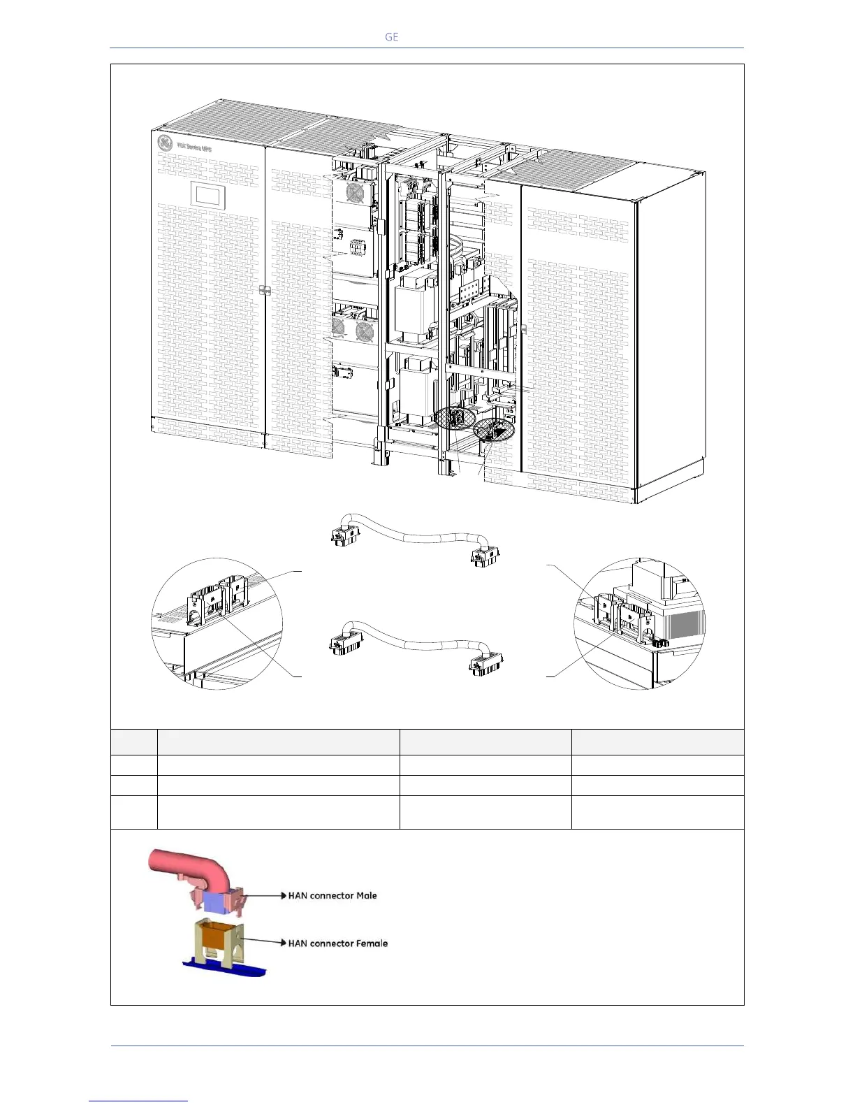
TLE Series 800 - Control cables interconnection
Fig. 5.7.3-4 TLE Series 800 – Control cables interconnection
XD1 – HAN Connector male (46 poles)
XD2 - HAN Connector male (32 poles)
“In/Out Section cabinet”
XTR2 Connector
Fig. 5.7.3-5 Connection of hearting connectors (HAN connectors)
NOTE: All these connections must be performed by
QUALIFIED SERVICE PERSONNEL only.
Proper dressing needs to be done for each cable
assembly in order to reduce the stress.
All the cables must be sufficiently (at least 10cm/4")
away from all live parts.
Cable binders used to support the wiring must NOT be
overly tightened.
In/Out Section cabinet
XD1
(46 poles)
Power Section cabinet
XD2
(32 poles)
XD1
(46 poles)
XD2
(32 poles)
XD1 Connector (46 poles)
XD2 Connector (32 poles)
1 2
TLES_800_S1_UPS connection cabinets_GE_03GB
1
2