GE_UPS_OPM_TLE_SCE_M60_M80_1GB_V020.docx
User Manual TLE Series 600 & 800 CE S1
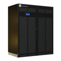
BATTERY SCREEN
Voltage
The battery voltage.
Current
The battery current (negative values
correspond to the discharge of the
battery).
Temperature
The temperature of the battery (“XXX”
indicates sensor disabled).
Autonomy
The estimated backup time with the present Load.
Note: the backup time is computed given the unit load.
Therefore, during IEMi Operation Mode, on-line units may show a reduced backup time.
However, following a power outage, all inverters are forced on-line.
Therefore, during battery operation every unit shows the true battery autonomy.
Charge level
The battery charge level.
On battery time
Total operating time of the UPS on battery (in hours).
BATTERY DISCHARGE COUNTER / Residual Charge Level
The number of discharges combined with the percentage of the available residual battery capacity at
the time utility power is restored.
Battery charger status
Battery charge status (Off / Float / Boost).
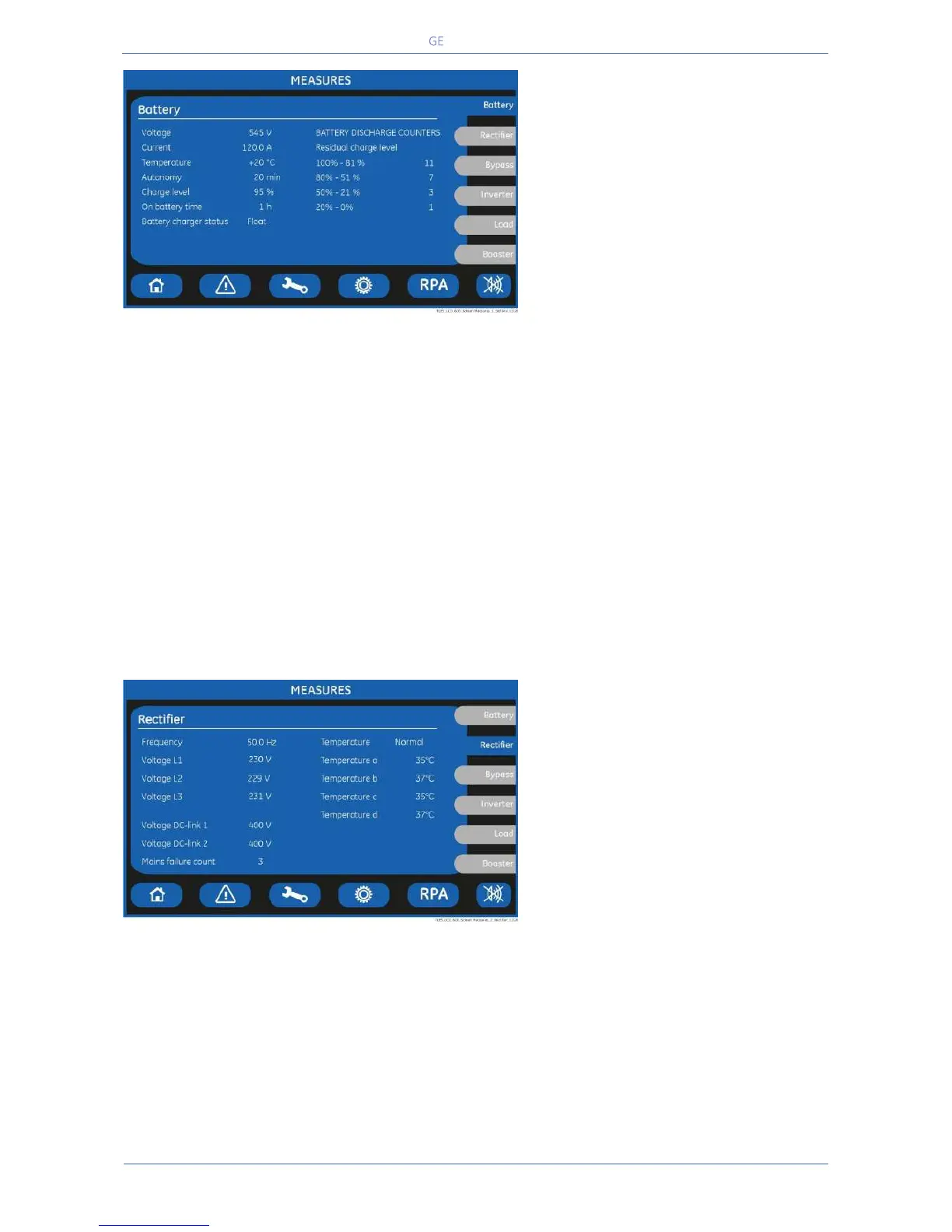
RECTIFIER SCREEN
Frequency
The input frequency of the Rectifier.
Voltage L1 / Voltage L2 / Voltage L3
3-phase Mains voltage PHASE /NEUTRAL.
Voltage DC-link 1
DC-Link 1 voltage.
Voltage DC-link 2
DC-Link 2 voltage.
Main failure count
Total number of times a gap of mains in the Rectifier has been reordered.
Temperature
Rectifier inlet L1 Coil temperature (Normal / Alarm).
Temperature a / b / c / d
a- Temperature of the Rectifier bridge (lower left module).
b- Temperature of the Rectifier bridge (upper left module).
c- Temperature of the Rectifier bridge (lower right module).
d- Temperature of the Rectifier bridge (upper right module – only for 800 kVA).
 Loading...