GE_UPS_OPM_TLE_SCE_M60_M80_1GB_V020.docx
User Manual TLE Series 600 & 800 CE S1
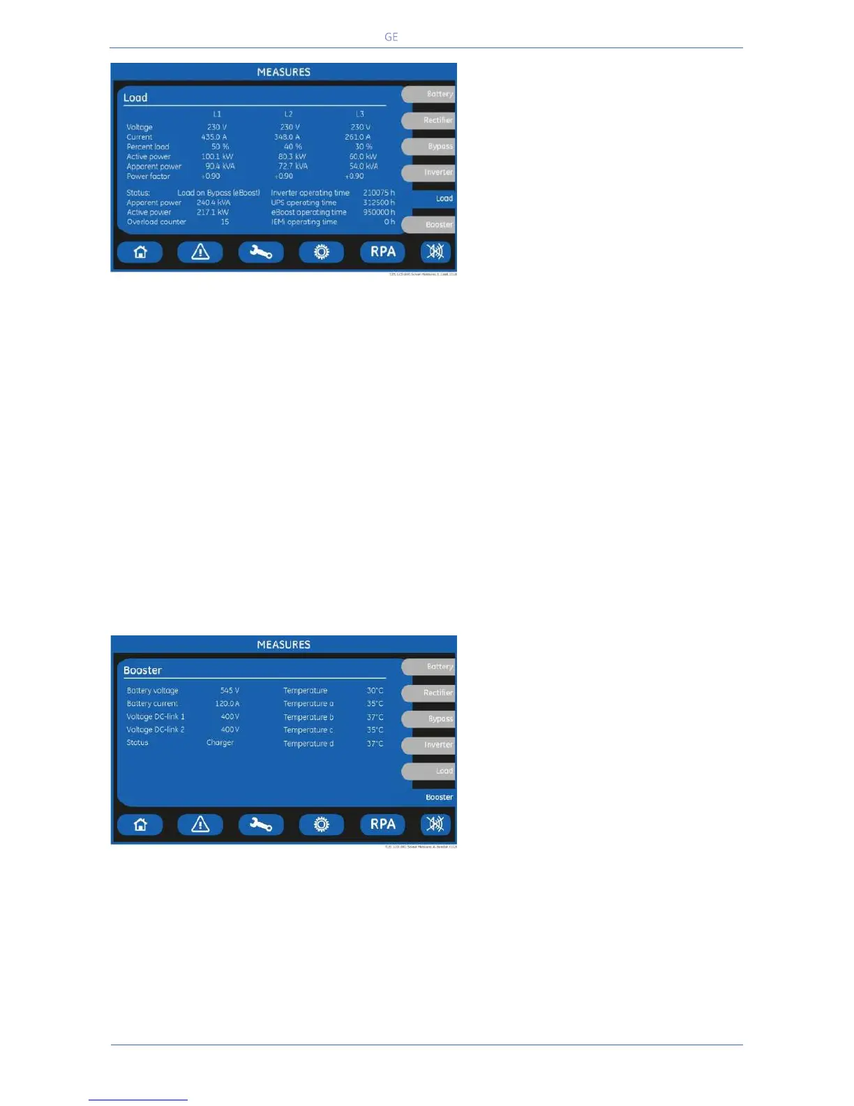
LOAD SCREEN
Voltage L1 / L2 / L3
Output voltage PHASE/NEUTRAL for each
phase.
Current L1 / L2 / L3
The output current as RMS values for
each phase.
Percent load L1 / L2 / L3
The output Load as percentage for each
phase.
Load active power (kW) for each phase.
Load apparent power (kVA) for each phase.
Load power factor: + inductive load / - capacitive load
Source of the power supplied to the Load.
Total apparent Load power (kVA).
Total effective Load power (kW).
Total number of detected output overloads.
Total operating time for the Inverter (in hours).
Total operating time for the UPS (in hours).
Total operating time for the UPS in eBoost™ Operation Mode (in hours).
This counter is displayed only when eBoost™ Operation Mode is available
(option).
Total operating time for the UPS in IEMi Operation Mode (in hours).
This counter is displayed only when IEMi Operation Mode is available (option).
BOOSTER SCREEN
Battery voltage
The battery voltage.
Battery current
The battery current (negative values
correspond to the discharge of the
battery).
Voltage DC-link 1
DC-link 1 voltage.
Booster status (Off / Booster / Charger).
Temperature of the 4
th
leg’s bridge.
Temperature a / b / c / d
a- Booster temperature (lower left module).
b- Booster temperature (upper left module).
c- Booster temperature (lower right module).
d- Booster temperature (upper right module – only for 800 kVA).