Handling and assembly
Spreading nozzles assembly (optional)
2018-9015-001
09-2016
66 / 192
5.21.2 Nozzles with manual directional valve
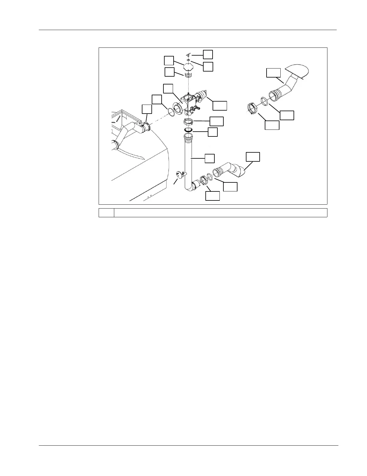
1
2
4
10
11
13
3
12
9
7
8
6
14
16
15
17
5
*
*
Bolted to the spreader
Manual directional valve assembly
● Place the O-ring (1) around the lid of the adapter (2);
● Place the adapter (2) on the anti-siphon end (3). Bolt the assembly;
● Place a restrictor (4) inside the top opening of the directional valve;
● Position a cap (5) on the restrictor. Secure it using ”T” handles (6) and flat
washers (7).
Bottom nozzle assembly
● Insert the seal (8) inside the vertical tube (9);
● Apply grade 2 PRECISION
TM
XL5 MOLY EP2 grease (or equivalent) on the
seal (8);
● Slide the vertical tube (9) on the bottom adapter (2) until it reaches the
adapter welded ring;
● Install a circle lock clamp (10) on the junction of the vertical tube and adapter;
● Insert the seal (11) into the spreading nozzle (12);
● Apply grade 2 PRECISION
TM
XL5 MOLY EP2 grease (or equivalent) on the
seal (11);
● Slide the spreading nozzle (12) over the vertical tube end (9) until it reaches
the welded ring on the vertical tube;
● Install a circle lock clamp (13) on the vertical tube and spreading nozzle
junction.
 Loading...