assembly and installation
Installing the control unit and power supply unit
7160-9001-560
01. December 2020
19 / 74
Installation steps
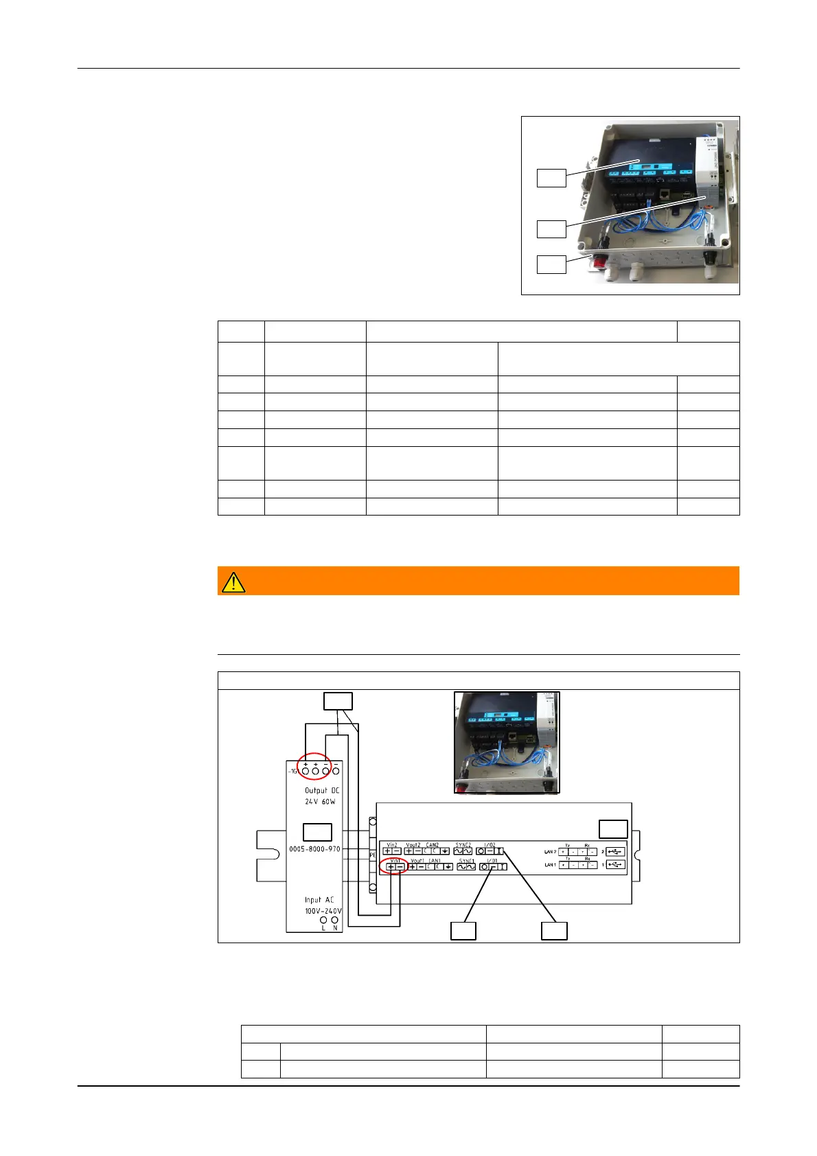
1. Install the control unit and power supply in
the housing
- Rail (a)
- Control unit (70)
- Electrical Requirements (40)
2. Secure the components with a PPE
terminal block and end plate (20, 30).
40
70
10
Item Part number Description Quantity
Control unit,
complete
VP8002 EU GEA x
10 7159-2853-050 Housing (complete) 276x230x136 1
20 0005-4622-890 Series terminal cage clamp 2-wire PE 1
30 0005-4617-890 End Plate for 2 cable terminals 2.5 mm² 1
40 0005-8000-970 Power supply unit 110-240V-AC to 24V-DC 60W 1
50 7160-6942-000
Cable harness
complete
CowScout 1
60 7038-9923-000 Kit of expansion parts cable gland M16, M20 1
70 7160-9067-260 Control unit VP8002 1
3. Wire components internally as shown
Warning!
Electrical Hazard!
► Do not connect the power supply until the installation work has been
completed!
Wiring diagram (VP8002)
40
50
70
a b
VP8002
- Connect the control unit to the power supply
- Connect the red and green lamps to the corresponding control outputs with
the cables provided
Indicator lights Out VP8002
a Red I/O1
b green I/O2