DF 7500
TL099-01-00-15
26-03-2015
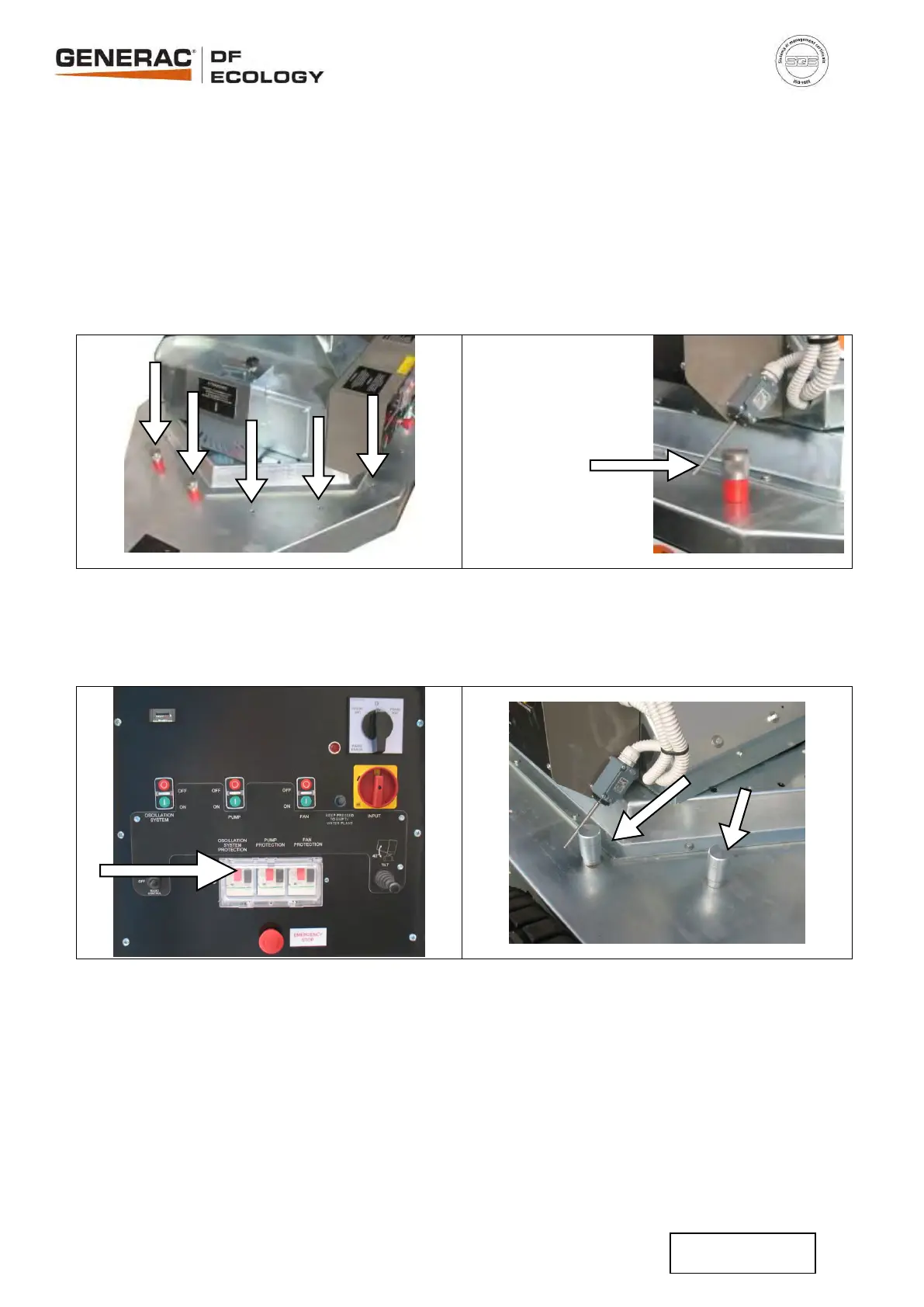
Des oeillets sont prévus sur le plateau,
(Fig. 34) qui en insérant les deux goupilles
prévues spécialement (Fig. 35) fournies avec
la machine, ils délimitent l’angle d’utilisation du
nébulisateur avec pivotement automatique et
permettent d’adapter l’utilisation avec précision
sans gaspiller l’eau.
On the chassis you can find a radial pattern
of threads (Fig. 34), let’s screw the pins in
two of these (Fig. 35) to set the nebulizer
working angle
Le microrupteur inverse la rotation toutes les
fois que l'on touche les goupilles (Fig.35).
The micro switch inverts turning direction
each time reaches the pins (fig.35).
(Fig. 34) (Fig. 35)
Mettre le disjoncteur du pivotement en position
“ON” (Fig. 36).
Switch the automatic oscillation system
circuit breakers to “ON” position (Fig. 36).
Sur le plateau deux goupilles sont fixées
délimitant la rotation du pivotement (Fig.37).
Two permanent limit switches define the
maximum working angle (Fig. 37).
(Fig. 36) (Fig. 37)
Allumer la radiocommande en appuyant sur la
touche ON (1) de la radiocommande (Fig. 38).
Start the radio control system pressing key
ON (1) of the remote control (Fig. 38).
Actionner les commandes depuis le
radiocommande pour démarrer la pompe (3) et
le ventilateur (4) (Fig. 38).
Push the buttons to start pump (3) and fan
(4) (Fig. 38).
Lancer le pivotement en appuyant sur (2) ou
(7) (Fig. 38) depuis la radiocommande pour
contrôler la direction d'utilisation du
nébulisateur, pour arrêter le pivotement ou
pour changer la direction, appuyer sur la
touche respective.
Start the oscillation system pressing (2) or (7)
(Fig. 38) to control or invert turning
direction, to stop oscillation press the
correspondent button.
Capteur pour le
pivotement
Microswitch

 Loading...