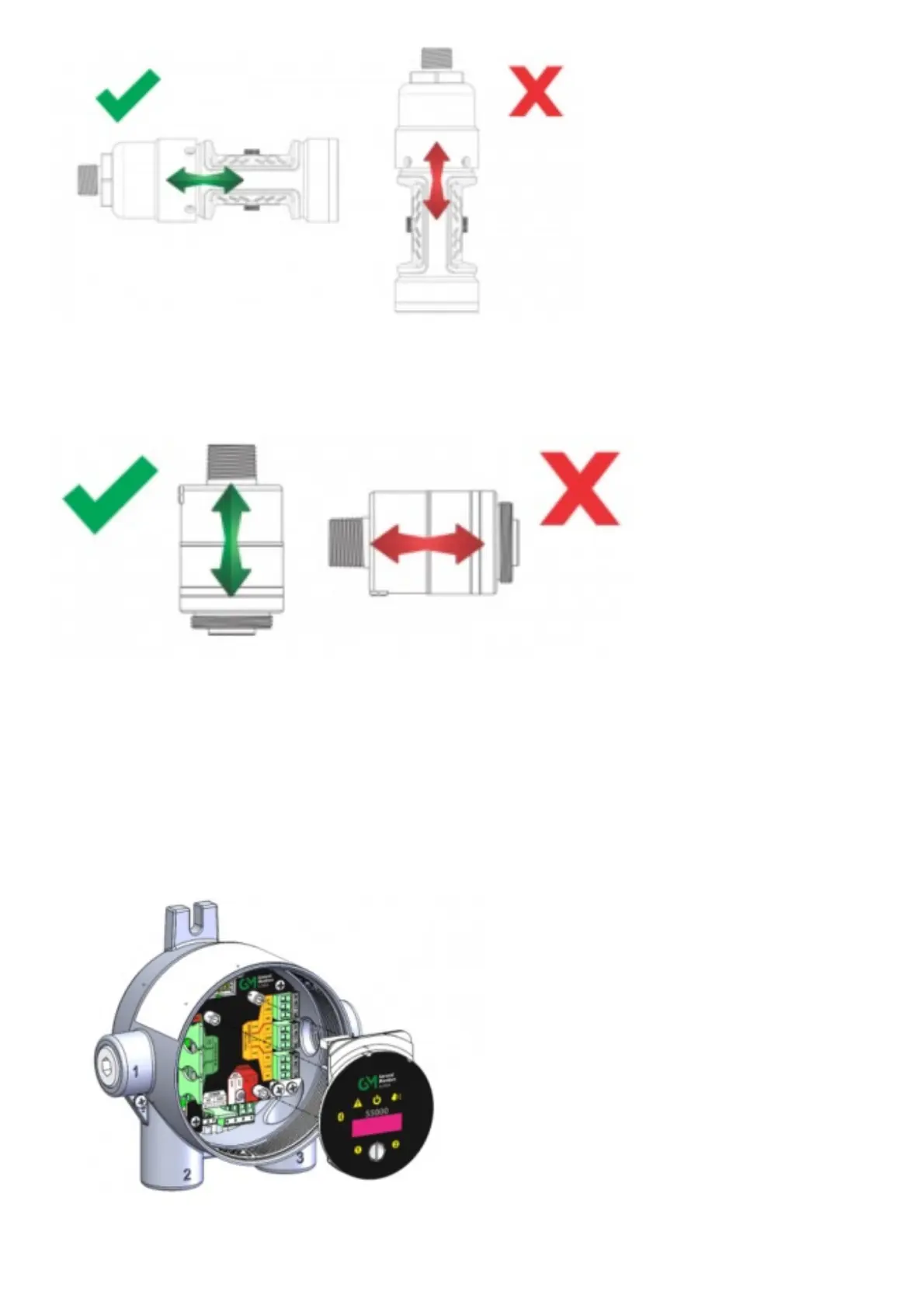
Figure 10 Correct and Incorrect Mounting Orientations for IR Sensor
All other sensors, including electrochemical, catalytic bead, oxygen, passive catalytic bead, and passive MOS should be mounted vertically with the gas inlet
pointed downward. If the sensor is not mounted with the gas inlet facing down, it is more likely to become clogged with particulate matter or liquids. Figure 11
shows the correct and incorrect mounting orientation for digital sensors. Passive catalytic bead and MOS sensors come already installed on the transmitter
housing.
Figure 11 Correct and Incorrect Mounting Orientation for Digital Sensors
3.4.4 Connecting Sensor to Transmitter Housing or Remote Junction Box
Digital and IR Sensors are shipped attached to the main enclosure. The main sensor input is provided via a four-terminal connection that provides a digital
interface for all sensor modules. Up to two sensors (excluding passive sensors) can be connected to a single transmitter with two analog outputs capable of
representing the readings of the individual sensors. Passive sensors are shipped already attached and electrically wired to the device. Only one passive sensor
can be used on a single S5000, and they are not interchangeable with other passive sensors or digital sensors. Consider the sensor dimensions when choosing a
mounting location for the transmitter or junction box.
To connect the sensor:
1. Loosen the set screw located on the lid using a 1.5 mm Allen wrench.
2. Turn the lid counter-clockwise to remove.
3. Pull out display module to expose terminal connections.
Figure 12 Terminal Connections
4. Route the cable from the sensor through a conduit entry hole in the enclosure so that the sensor is oriented in the correct position (see 3.6 Electrical Power
Connections for details).