1- When sizing a system’s 24 V supply, a 1 A inrush current with a 1 ms duration should be considered for each device on the power supply
Assumes transmitter was ordered with relays
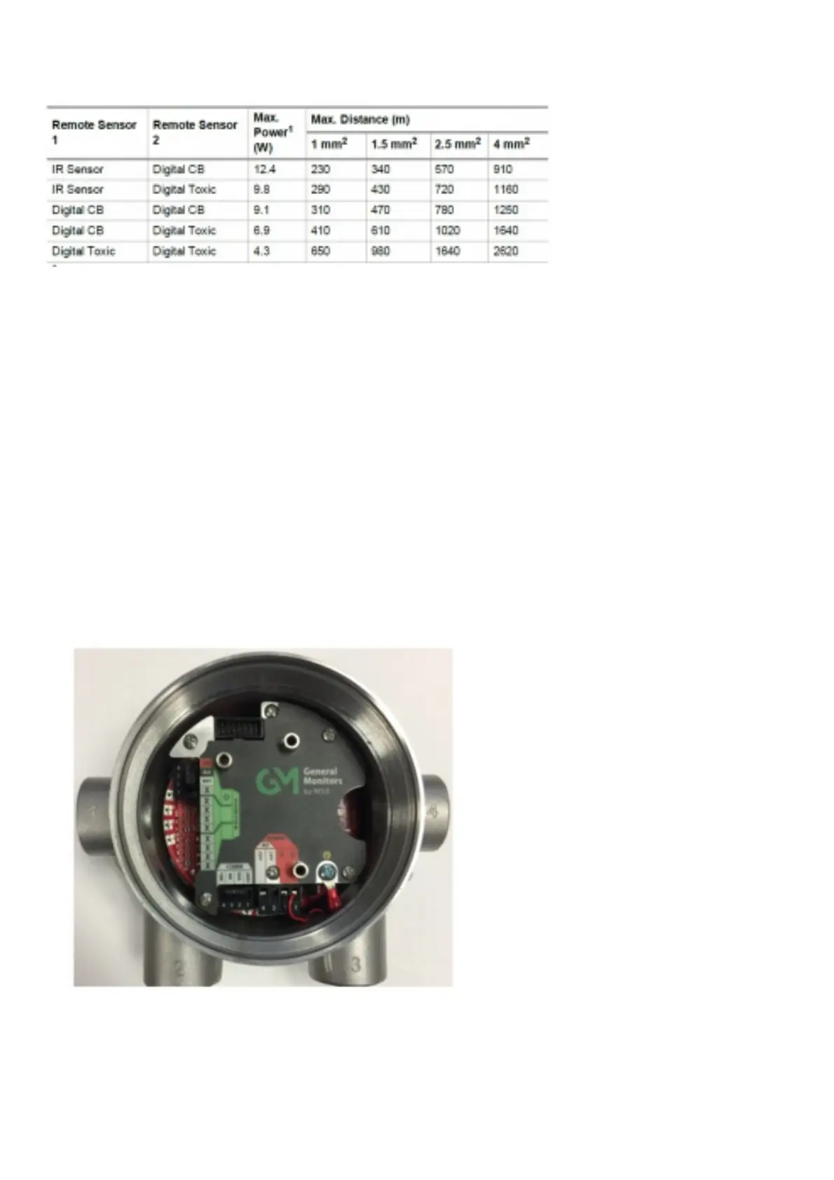
Table 6 Maximum Mounting Distance for Remote Sensors, Metric Units
1- When sizing a system’s 24 V supply, a 1 A inrush current with a 1 ms duration should be considered for each device on the power supply
Assumes transmitter was ordered with relays
3.6.5 Instructions for Power and Analog Output
Read all electrical warnings and wiring requirements before connecting power to the S5000.
Failure to follow this warning can result in serious personal injury or death.
Connector for HART analog output and power are provided to increase ease of connecting power. Connect power and remote sensor cable shields to shield
terminals on the main PC board. Provide shield terminations inside he sensor housing as indicated on the installation outline drawing.
1. Remove the cover by turning counter-clockwise.
2. Remove the display module to expose the wiring terminations and sensor connections.
3. Remove the 5.08 mm pitch connector for power supply. The power connector is larger than other 3.81 mm pitch connectors.
4. Use a small flat head screw driver to open wire entries on connector.
5. Insert wires to connector so that when installed each wire is in the correct location.
1. +DC
2. -DC
3. mA1 – analog output of sensor 1
4. mA2 – analog output of sensor 2
6. Tighten screws on connector and tug gently on wires to ensure they are secure.
7. Attach the connector to the board stack.
8. Make sure the appropriate wires are in the correct terminals.
9. Remove enough of the wire housing to expose the 3-4 inches of the cable shielding, but do not expose so much that it goes beyond the cable entry.
10. Attach the cable, shielding exposed, to the grounding point.
11. Replace the display module. Push firmly on the board stack where indicated.
12. Replace the S5000 cover by turning clockwise. Be sure to align threads to avoid cross-threading.
Figure 27 Connecting Power and Grounding Cable
NOTICE
Ensure that the electronics assembly is fully engaged in the mounting holes. If not fully seated, the touch interface
performance can be negatively affected.
Care must be taken to ensure the S5000 inside glass surface glass is free of smudges/dirt and grease. Dirt and grease can
interfere with the touch interface of the display.
S5000 Installation Outline Drawings