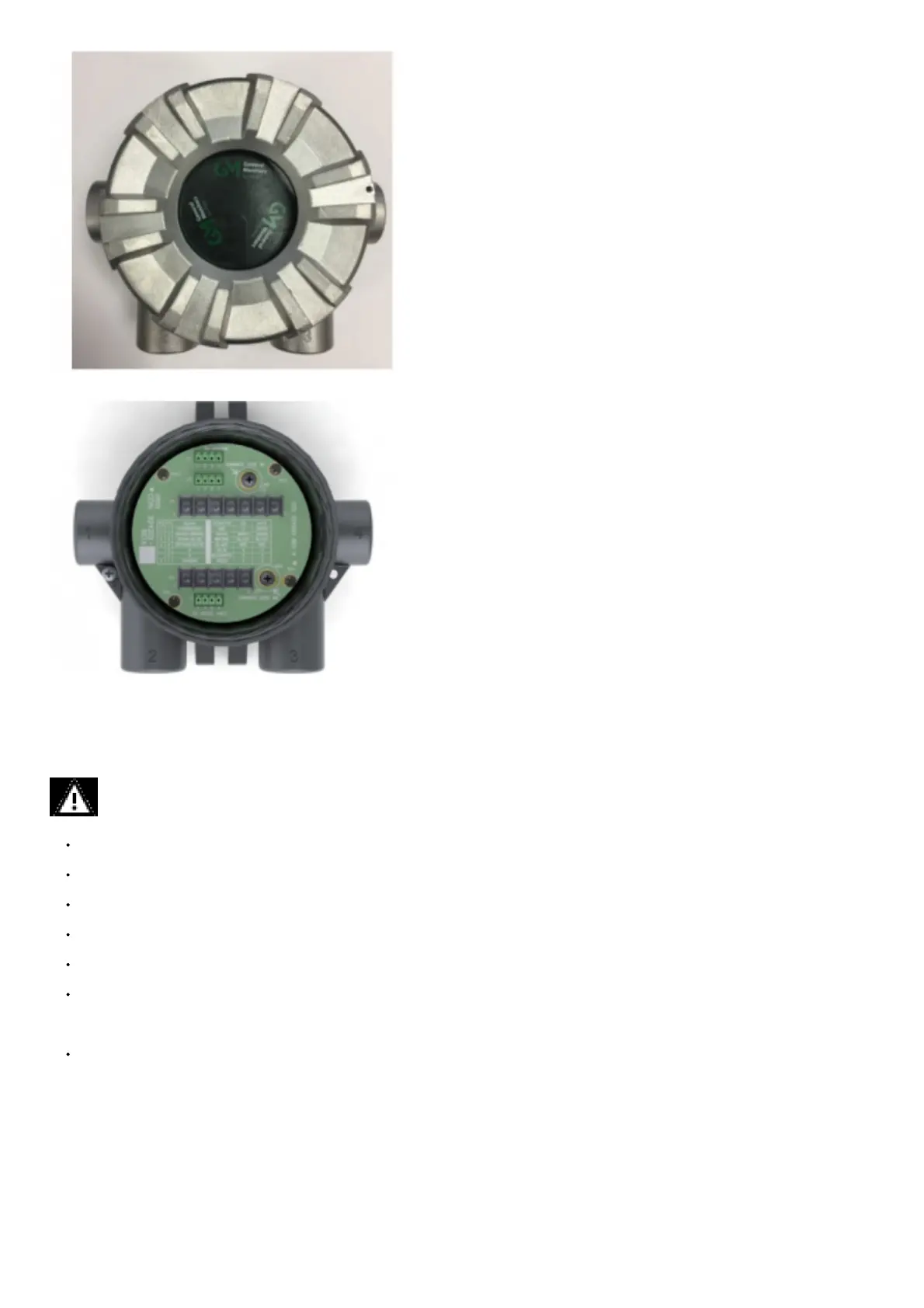
Figure 22 Junction Box
Figure 23 Junction Box Electrical Connections
3.6 Electrical Power Connections
3.6.1 Electrical Warnings – Read before Connecting Power
WARNING!
Before wiring the S5000 transmitter, disconnect the power source supplying the transmitter and ensure no hazardous atmosphere present; otherwise,
electrical shock or ignition of hazardous gases could occur.
Install wiring in accordance with the electrical code of the country in use, the local authority having jurisdiction and these installation instructions, as
applicable.
Do not make any connections to the S5000 main board or junction box input, output, and relay connections while under power. Making connections under
power could lead to electrical shock or ignition of a hazardous atmosphere.
Ensure that water and dirt are not able to enter the unit via the wire or conduit. If the unit is installed in a location known to be wet or damp, it is good practice
to loop or bend the entry into the unit that prevents water incursion.
The internal grounding terminal (located on the interior metal board stack plate) must be used for equipment grounding. The external grounding terminal is
only to be used as a supplemental bonding connection where local authorities permit or require such a connection.
As part of the product certification, it was verified that optional communication functions of this gas detection instrument while operating at the maximum
transaction rate do not adversely affect the gas detection operation and functions of the instrument. The product certification, however, does not include or
imply approval of the SafeSwap feature, communications protocol or functions provided by the software of this instrument or of the communications
apparatus and software connected to this instrument.
Follow the warnings below when removing or replacing sensors. Reference Figure 3 for component overview.
– Never remove or replace a sensor body assembly or an IR Sensor while under power or when explosive hazards are present.
– Confirm that the area is free of explosive hazards before removing or replacing an XCell Sensor under power.
– To remove an XCell Sensor, unscrew XCell Sensor three full turns, wait 10 seconds, and then remove the XCell Sensor completely.
Failure to follow these warnings can result in serious personal injury or death.
3.6.2 Retrofit Applications with S4000CH, S4000TH, or TS4000H
The S5000 was designed to be easily retrofitted with existing S4000CH, S4000TH, and TS4000H wiring. When replacing an existing S4000CH, S4000TH, or
TS4000H with the equivalent S5000 sensor technology, the following items need to be checked in order for the S5000 to operate:
1. Wire gauge needs to be 18-14 AWG
2. Sufficient power must be supplied to the S5000 in accordance with the maximum wire lengths. (See the tables in