3.6.4 Power Load Requirements and Maximum Mounting Distances)
If these requirements are met, performance of the S5000 should meet the noise immunity standard equivalent of the S4000CH, S4000TH, and TS4000H
using the existing wiring; However, the installation may not meet the latest EMC EN50270 noise immunity standard that the S5000 meets with the grounding
and wiring scheme as indicated in this manual
and corresponding I/O drawing.
3.6.3 Electrical Hardware Requirements
Braided shielded, twisted pair, instrument quality wire or cable should be used to minimize the possibility of noise interference and contact with other voltages.
Selection of shielded cable must comply with local requirements. Conduit, in addition to braided shielded wire, may also be needed in areas where a large
amount of electrical noise is
expected. All cable shields should be terminated to earth ground at one end only. The S5000 has a four-wire power terminal, one four-wire communication
terminal, and three four-wire sensor terminals. Relays can be added as an option. Terminals for power and relays can take wires up to 12 AWG while all other
terminals take wires up to 14 AWG. Four conductors are also required for the S5000 remote junction boxes.
Incoming power and signal cables should be a braided shield cable such as Alpha Wire 3248 or equivalent. The braided shield must be terminated to the board
stack as shown in Figure 27 , or alternatively, the earth ground at the user’s power source location.
An external Class 2 power supply is required to supply 12-30 VDC to the S5000. Incoming power and signal cables should be a braided shield cable such as
Alpha Wire 3248 or equivalent.
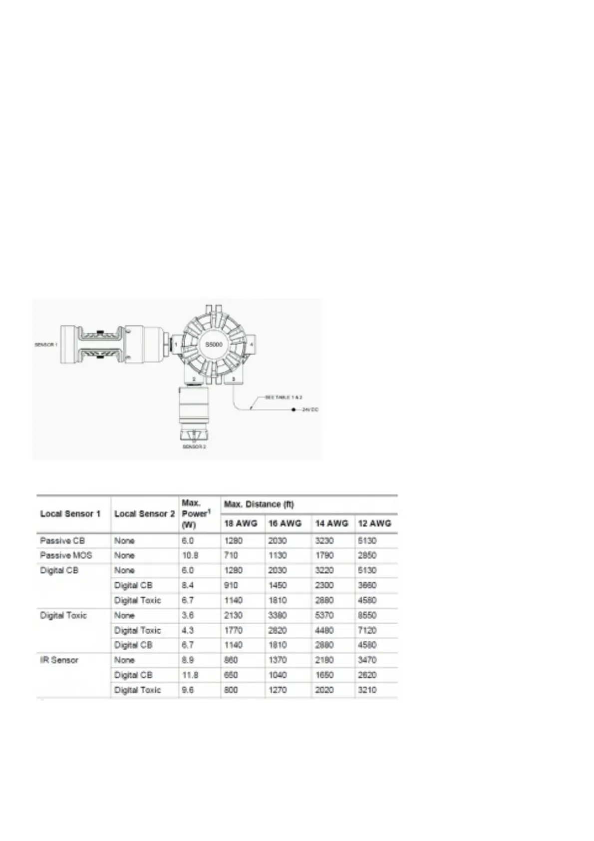
3.6.4 Power Load Requirements and Maximum Mounting Distances
Consider future needs when selecting cable size and power supply. The maximum distance between the S5000 transmitter and the power supply depends on the
sensor configuration (sensing technology and one or two sensors), wire gauge, and the power supply voltage. The table below outlines the maximum transmitter
mounting distances. First determine if the
sensor(s) will be locally or remotely mounted. Then choose sensor type(s). The corresponding maximum power and mounting distances by wire gauge are
shown.
Figure 24 Local Sensors
Table 1 Maximum Mounting Distance for Local Sensors, Imperial Units
1- When sizing a system’s 24 V supply, a 1 A inrush current with a 1 ms duration should be considered for each device on the power supply
Assumes transmitter was ordered with relays
Table 2 Maximum Mounting Distance for Local Sensors, Metric Units