Specific Conditions of Use S5000 Transmitter
Under certain extreme circumstances, the non-metallic parts incorporated in the enclosure of this equipment may generate an ignition-capable level of
electrostatic charge. Therefore, the equipment shall only be cleaned with a damp cloth.
This fixed equipment apparatus is exclusively designed for field mounting in the vertical orientation with restrictions placed around the conduit entry
locations permitted for connection of both the Digital Sensor and IR Sensor. The equipment is subject to the installation and orientation requirements
defined in the product manual.
The flameproof joints shall not be repaired.
The S5000 Gas Monitor fixed gas detection system complies with EN 50271 (clause 4.8, safety integrity assessment
excluded from the assessment).
S5000 Junction Box
Under certain extreme circumstances, the non-metallic parts incorporated in the enclosure of this equipment may generate an ignition-capable level of
electrostatic charge. Therefore, the equipment shall only be cleaned with a damp cloth.
The flameproof joints shall not be repaired.
The S5000 Gas Monitor fixed gas detection system complies with EN 50271 (clause 4.8, safety integrity assessment excluded from the assessment).
Digital Sensor
Under certain extreme circumstances, the non-metallic parts incorporated in the enclosure of this equipment may generate an ignition-capable level of
electrostatic charge. Therefore, the equipment shall only be cleaned with a damp cloth.
The flameproof joints shall not be repaired.
If the sensor is uninstalled, the equipment instruction manual shall be referenced prior to reinstalling.
The Digital Sensor is provided with a ¾“ NPT thread and shall only be connected to a suitably certified enclosure. The installation to the certified enclosure
shall be with five fully engaged threads, tightened wrench-tight.
The Digital Sensor shall be connected directly to a suitably certified junction box or instrument for the hazardous area of installation and thereby provide Ex
protection for the flying lead connections.
For combustible gas detection performance applications, the appropriate Digital Sensor model number shall only be used to construct the S5000 Gas
Monitor fixed gas detection system; mounted onto either the S5000 transmitter or S5000 Junction Box enclosures and receive power and control from the
transmitter.
The Ingress Protection rating is exclusively based upon the installation instruction for orientation specified in the operating manual.
The Digital Sensor shall only be installed for external connection to suitably certified equipment (transmitters) providing transient protection set at a
maximum transient overvoltage of 119 V (140% of 85 Vpeak).
Not performance approved for Class II, Class III, Zone 21. The Digital Sensor may become clogged and not detect gas or warn user of inability to detect
gas. Regularly visually inspect the sensor and apply gas to ensure a clear gas path to the sensor if there is potential that blockage has occurred. Conditions
that may lead to blockage, including but not limited to snow, ice, water, dirt, dust, or insects necessitate more frequent inspections.
Failure to follow these warnings can result in serious personal injury or death.
10 Appendix: HART Specific Information
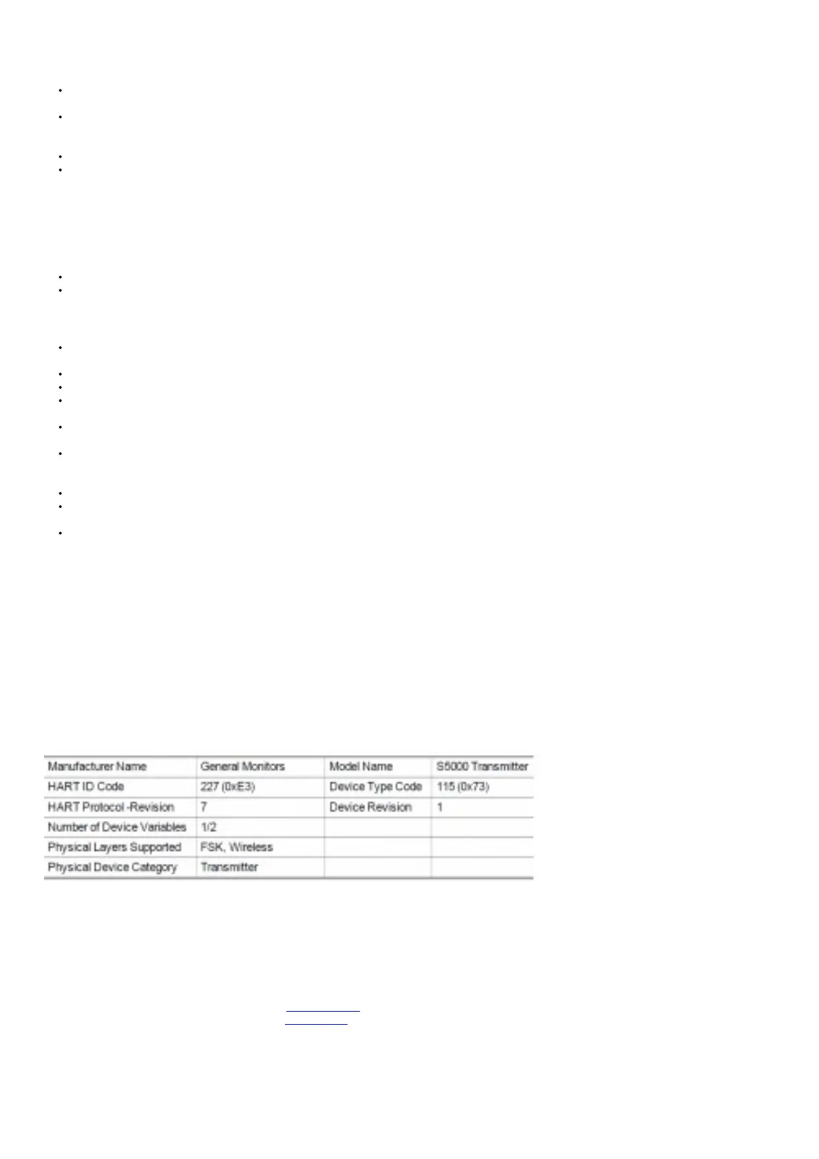
The S5000 Gas Monitor is available with an optional HART (Highway Addressable Remote Transducer) output communications protocol. With this option, the
S5000 complies with HART Protocol Revision 7 and uses the 16-bit manufacturer and device codes. This document specifies all the device specific features and
documents HART Protocol implementation details (e.g., the Engineering Unit Codes supported). These specifications assume the reader is somewhat familiar
with HART Protocol requirements and terminology. This specification is a technical reference for HART-capable HOST Application Developers, System
Integrators and knowledgeable End Users. It also provides functional specifications (e.g., commands, enumerations and performance requirements) used during
Field Device deployment, maintenance, testing, and operations. It is recommended that the 4- 20 mA output be the primary gas monitoring signal. The HART
signal can be the secondary method.
Table 22 Device Identification
The 3.5 mA version of the IR400 is not compatible with the S5000
Read More About This Manual & Download PDF:
General Monitors S5000 Gas Monitor User Manual – Optimized PDF
General Monitors S5000 Gas Monitor User Manual – Original PDF
Related Manuals
1. General Monitors S5000 Gas Detector User Manual General Monitors S5000 Gas Detector User Manual – Optimized PDF...
2. Ultima X5000 Gas Monitor User Manual Ultima X5000 Gas Monitor User Manual – Optimized PDF Ultima...
3. Ultima X5000 Gas Monitor System User Manual Ultima X5000 Gas Monitor System User Manual – Optimized PDF...