84
2.3.2 Trigger
*Attention
Install the spark plug on the air cylinder head and inspect with normal compression pressure.
Remove the 6P joint of CDI group, and connect a peak
voltage diverter between the trigger of 6P joint (blue/white
terminal)to the wire and the 4P joint(black terminal). Press
the startup electrical machinery or step on the actuating lever
to measure the peak voltage of the trigger.
Connecting method: positive pole connected with blue/white
line, and negative pole connected with black line.
Minimum voltage:1.7V or above.
*Attention
The metal area of the avometer prod mustn't be touched by
fingers to prevent electroshock.
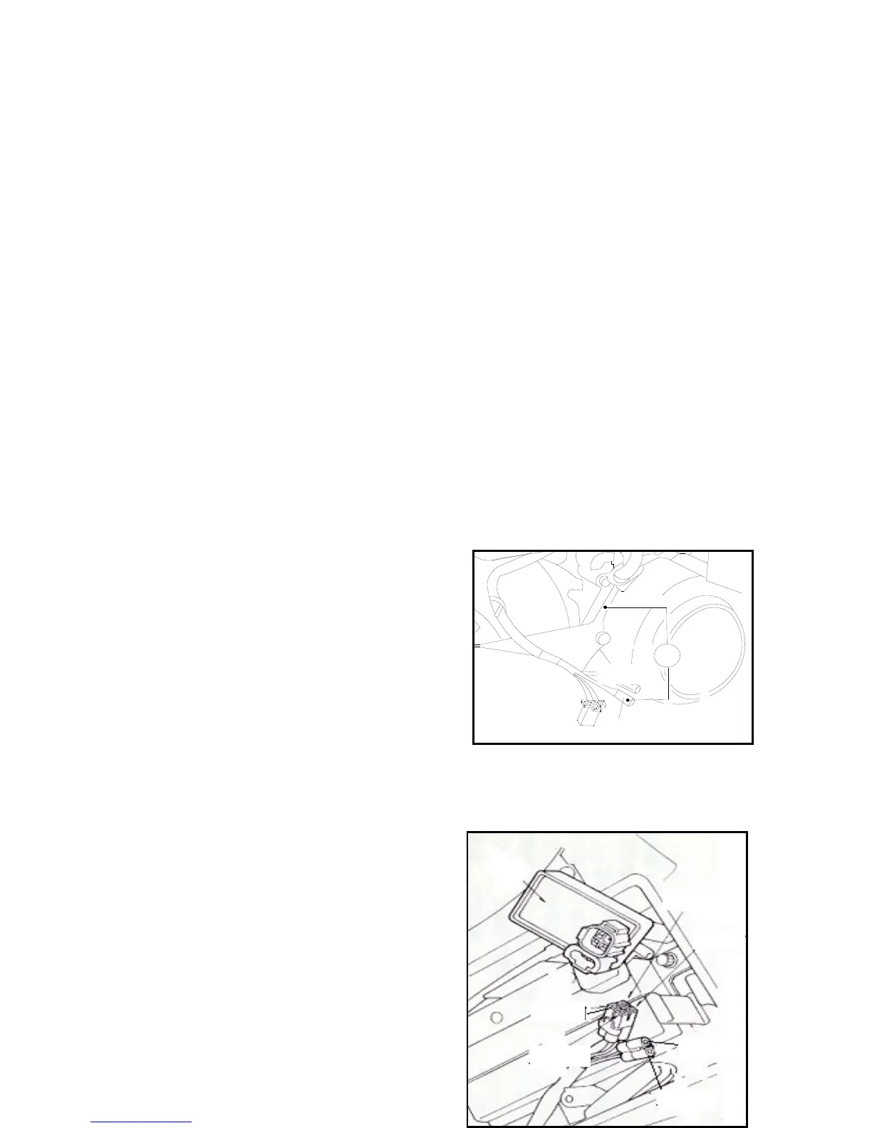
If the peak voltage of the CDI terminal has an abnormal value,
disassemble the right body guard and the alternator joint.
Connect the trigger(blue / white) with the diverter.
•If the tested voltage of CDI is abnormal whereas the tested
voltage at the alternator is normal, poor contact or broken line
can be determined.
•If both are abnormal, bad act of the trigger can be determined. Please refer to inspection of the troubleshooting
table.
2.4 CDI group
2.4.1 System inspection
System inspection.
Disassemble the CDI group and inspect the parts related
with the ignition system at the wire terminal.
蓝/ 白
Ω
白/ 绿
Blac