Installation
2
2-14 223 Sample Changer User’s Guide
Rear Panel Connections
Input/Output Ports
You can use the input and output contacts found on the rear panel of the sample changer to control peripheral devices. Refer
to the Rear Panel Diagram
on page 2-12 for the location of the input/output ports.
Inputs
The input terminal block of the sample changer has four contacts. All of the inputs are paired, and each of the pairs includes a
GROUND reference ( ).
The contact input pairs are labeled A, B, C, and D.
A contact is connected if it has a short across the input or is held low by a TTL output or other device.
Never connect voltages higher than 5V DC to an input. When using TTL signals, be sure to match ground connections.
Outputs
The output terminal block has four contacts. All of the outputs are paired.
The contact outputs are labeled 1, 2, 3, and 4.
Pins 1 and 2 supply ground and a +12V DC output. Do not use this output unless the receiving device can accept 12V power.
Do not allow more than 500 mA load.
Pins 3 through 10 are paired, isolated-relay contact closures.
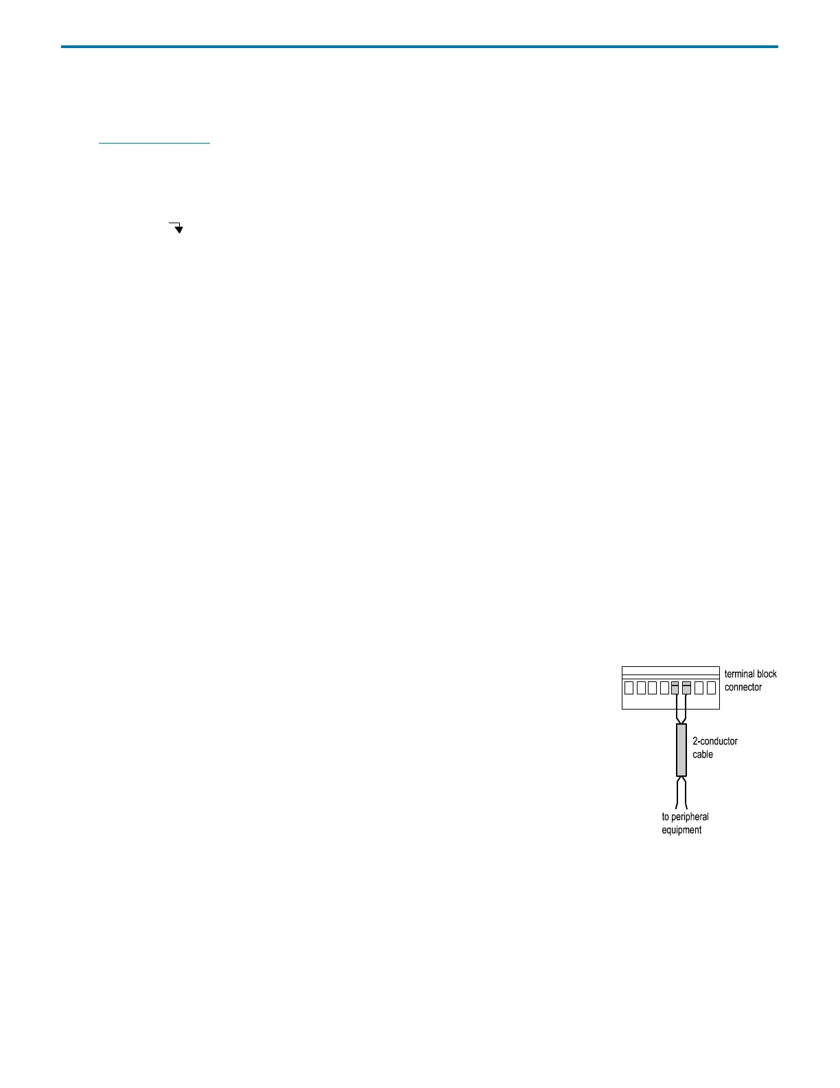
Make Connections
The following are needed to make connections:
• terminal block connector
• 2-conductor cable (22–30 gauge for each wire)
• wire insulation stripper
•small-blade screwdriver
To make connections using the 2-conductor cable:
1 Cut the cable into pieces of appropriate length.
2 Strip about 3 mm of insulation from each end of the cable.
3 Locate the appropriate green terminal block connector in the accessory package. The
connector for inputs has eight slots while the one for outputs has ten.
4 Insert each wire into the appropriate slot on the terminal block connector. Push the wire all the
way in and then tighten its corresponding pin screw.
Note: When making connections, be sure to maintain the correct orientation of the terminal block connector relative to the
port. This is especially important if making connections to the +12V DC output.
5 Connect the terminal block connector to the sample changer. Push the connector in as far as it will go. It is designed to fit
snugly into its receptacle.
6 Connect the opposite ends of the wires to the other device(s). Be sure to match
GROUND connections.
7 Label each cable to identify the purpose of the connection.
 Loading...