83
MDE-LEDInetworkITS-server-4078V1.3
2.2. OUTPUT CARDS CONFIGURATION
2.2.1. Introduction
Your LEDI Network ITS is provided with up to 3 output cards in 1U (4 for LEDI Network
DCLS). Each output card is tightly synchronized on either the NTP time code received
from the NTP server or the GPS or the IRIG B input card. Each card acts as a kind of
translator that receives time from the main synchronization source and output specic
time code.
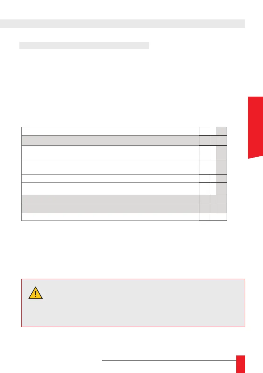
Currently, there are 9 kinds of cards:
NTP/SNTP
N
4 sorties AFNOR NFS 87500/IRIGB 1000HZ
H
4 sorties PPS,PPM, PPH, PP2S, DCF (TTL, differential TTL,
Phototransistor)
P
4 sorties PPS,PPM, PPH, PP2S, DCF (TTL, differential TTL,
Static Relay)
Q
4 sorties DCLS (TTL, differential TTL, Phototransistor)
T
4 sorties DCLS (TTL, differential TTL, Static Relay)
V
4 sorties Serial ASCII RS 232
A
4 sorties Serial ASCII RS 422, RS485
R
SMPTE S
When you receive this product from Gorgy Timing, all the output cards are congured to
output UTC time and time is constant all along the year (no Day Saving Time correction).
The display is managed as an output cards and can be congured in the same way.
2. FULL SETUP
Important.
The signal format on PPS cards and DCLS cards can be changed
to TTL, differential TTL (RS422) or phototransistor / static relay
(depending of the card type). See Appendix D – MAINTENANCE -
2.Output card switches verication.
ENGLISH