34 GMC-I Messtechnik GmbH
Test Sequence
Prerequisite for Testing
The measurement of insulation resistance may not be
conducted on protection category I devices which have
not passed the protective conductor resistance test.
The insulation test cannot be performed for all DUTs, for
example electronic devices, EDP equipment, medical
devices etc. Leakage current measurements must be
performed for these DUTs (see Section 8.7).
Observe the notes in the service instructions.
In order to prevent damage to the instrument, measure-
ment of insulation resistance may only be performed be-
tween application parts, measurement inputs or
interfaces and the protective conductor or the housing if
the instrument is laid out for measurements of this type.
Touching the DUT During Measurement
Testing is conducted with up to 500 V, and although cur-
rent is limited (I < 3.5 mA), if the DUT is touched electrical
shock may occur which could result in consequential ac-
cidents.
Switch Settings at the DUT
All switches at the DUT must be set to the on position
during measurement of insulation resistance, including
temperature controlled switches and temperature regula-
tors as well.
Measurement must be performed in all program steps
for devices equipped with program controllers.
➭ Set the rotary switch to the R
ISO
position.
➭ Select the measurement type:
– By setting the parameters
or
– Directly via the Measurement Type key
➭ Select the test voltage.
The Up– and Up+ keys provide you with direct access to the
test voltage parameters: each time this key is pressed, the
setpoint value shown in the measuring window, Up(set), is re-
duced or increased by 10 V.
➭ Connect the DUT to the test socket.
➭ Start the test: press the START/STOP key.
➭ Switch the device under test on.
The measurement is disabled if a voltage of greater than
25 V is measured between the terminals.
➭ The measured values are displayed. The measured
value recording symbol shown at the right appears.
Each time this key is pressed, the currently displayed
measured value is saved to buffer memory.
➭ Turn off the device under test.
Removing the Connector Cable
Do not remove the DUT’s connector cable until the test
has been stopped, in order to assure that the capacitors
have been discharged.
➭ End the test: press the START/STOP key.
The save symbol appears (floppy disk showing the
number of measured values stored to buffer memory)
and prompts you to save the measured values to an ID
number.
➭ Read the measured values and compare them with the
table of permissible limit values.
➭ Press the ESC key in order to discard the measured
values stored to buffer memory and acknowledge by
pressing the key shown at the right.
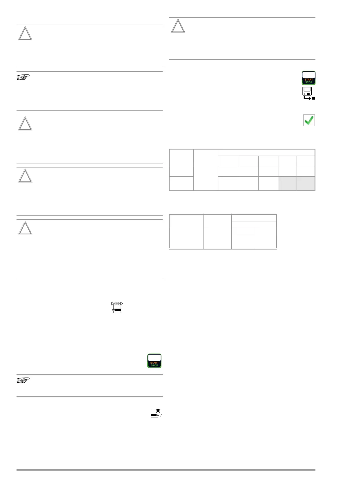
Minimum Permissible Limit Values for Insulation Resistance
* With activated heating elements
(where heating power > 3.5 kW and R
INS
< 0.3 MΩ: leakage current measurement
is required)
Notes
Insulation resistance and/or leakage current must be measured
by contacting all exposed, conductive parts with test probe P1 for
protection category II and III devices, as well as for battery pow-
ered devices.
Batteries must be disconnected during testing of battery powered
devices.
Test Standard Test voltage
R
INS
LN → PE
LN →
Probe
Probe →
PE
PC III Heating
VDE 0701-
0702:2008
500 V
1MΩ 2MΩ 5MΩ 0.25 MΩ 0.3 MΩ *
DIN EN 60974-4
VDE 0544-
4:2017-05
2MΩ 5MΩ 5MΩ
Test Standard Test voltage
R
INS
PC I PC II
IEC 62353
(VDE 0751-1)
500 V
2MΩ 7MΩ
BF or CF BF or CF
70 MΩ 70 MΩ

 Loading...


