58 GMC-I Messtechnik GmbH
10 Test Sequences
Status upon shipment (default setting)
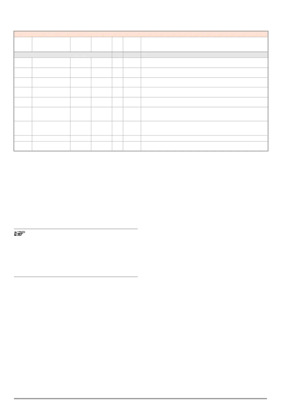
* Assuming the respective sequence parameter is preset to “on”
** Additional testing of conductive/metallic parts which are not connected to the protective conductor
Auto = automatic detection, see page 61
10.1 General
If the same sequence of single tests will be run frequently (one
after the other with subsequent report generation), for example as
specified in the standards, it’s advisable to make use of test
sequences (also called measuring sequences).
Limit values have been entered for test sequences in accordance
with the standards. And thus a go/no-go evaluation takes place
during measurement based on worst-case assessment. If the
momentary measured value is displayed in green, it lies within the
limit values specified in the standard. If the measured value is red,
is does not fulfill the requirements set forth in the standard.
The go/no-go evaluation of the measured values is per-
formed with greater accuracy than the value which
appears at the display, which may lead to the fact that,
due to the missing decimal places, a measured value
which appears at the display may seem to correspond
exactly to the limit value although it’s highlighted in red (as
a limit value violation) due to the places to the right of the
decimal point.
If the measured value is orange, further entries are required after
the test step (e.g. cable length), which are decisive as to whether
or not the test has been passed. Even if the DUT fails just one sin-
gle measurement, the test sequence is aborted and testing in
accordance with the selected standard is failed.
Automatic test sequences are run in rotary switch positions
AUTO, as well as A1 through A8.
Test sequences A1 through A8 and AUTO are preconfigured at
the factory.
We recommend assigning frequently used test sequences to A1
through A8, and conducting special sequences for which param-
eters often need to be adjusted in the AUTO switch position.
The measurements are evaluated automatically by the test instru-
ment. Evaluation is based on the worst-case and, depending on
settings, in consideration of measuring uncertainty.
Specifications for the test sequences can be entered to the test
instrument in two different ways:
• SETUP switch position: general settings can be entered which
apply to all test sequences (regardless of the respectively
selected standard).
• Switch positions AUTO and A1 to A8: classification and sequence
parameters can be entered which only apply to the selected
switch position.
Test Sequences in the AUTO Switch Position
The following test sequences are included as a standard feature
with the SECUTEST BASE(10) and the SECULIFE ST BASE(25) in rotary
switch positions AUTO and A1 to A8:
• DIN VDE 0701-0702
Periodic testing and testing after repair and modification of
electrical equipment
• IEC 62353
Medical electrical equipment – Recurrent test and test after
repair of medical electrical equipment (applied parts with test
probe P1)
• IEC 60974-4
Arc welding equipment – Part 4: Periodic inspection and test-
ing (voltage measurement with test probe P1 without electrical
isolation) One pole of the voltage to be measured must be
connected to PE at the mains.
The individual sequences are selected with the softkeys.
User-Defined Test Sequences
Up to 24 * customer-specific (user-defined) test sequences can
be saved to the test instrument and assigned to rotary switch
positions AUTO and A1 to A8. The sequences are created at the
PC with the help of IZYTRONIQ software (up to firmware 1.7.2:
Sequence Designer software).
The measurements and parameters available in your SECUTEST
version are loaded from the test instrument and made available in
the PC software for this purpose. Finally, the created test
sequence can be loaded directly to the SECUTEST... (prerequi-
site: database extension, feature KB01, “Z853R – SECUTEST
DB+”) and saved to the computer as an XML file. As a rule, cus-
tomer-specific (user-defined) test sequences are identified with a
preceding asterisk (*) in the SECUTEST user interface.
* As of firmware version 2.0, a total of 24 user-defined test sequences can be loaded
to the test instrument with feature KB01, “Z853R – SECUTEST DB+”.
Automated test sequences, rotary switch level: orange
Switch
Setting
Standard /
Test Sequence
Measure-
ment Type
Connec-
tion
Type Protec-
tion
Category
Freely configurable depending on the selected configuration (protection
category, type of application part)
Preconfigured (freely adjustable) test sequences
A1
VDE 0701-0702 Passive Test socket
PC I + PC II
**
Short-circuit test * – visual inspection * –
RPE * – RINS PC I * –
RINS
PC II
**
– IPE Alt. – IT
Alt.
**
– function test *
A2
VDE 0701-0702 Active Auto
PC I + PC II
**
Short-circuit test * – visual inspection * –
RPE * – RINS PC I * – RINS PC II
**
– IPE NL – IT NL
**
– IPE LN –
IT LN
**
–
function test *
A3
VDE 0701-0702-EDV
Active
Auto
PC I + PC II
**
Short-circuit test * – visual inspection * –
RPE * – IPE NL – IT NL
**
– IPE LN – IT LN
**
–
function test *
A4
IEC 62353 (VDE 0751) Passive Test socket BF
PC I + PC II
**
Short-circuit test * – visual inspection * – RPE * – RINS PC I * – RINS PC II+AP * – RINS LN < >
F * – RINS PE < > F * – IE SK I – IT Alt.
**
– IA BF – function test *
A5
IEC 62353 (VDE 0751) Active Auto BF
PC I + PC II
**
Short-circuit test * – visual inspection * – RPE * – RINS PC I * – RINS PC II+AP * – RINS LN < > F *
RINS PE < > F * – IE NL PC I – IT NL ** – IA NL BF – IE LN PC I – IT LN ** – IA LN BF – function test *
A6
IEC 60974-4 Active Auto
PC I + PC II
**
Short-circuit test * – visual inspection * –
RPE * – RINS PC I – RINS welding circuit – RINS
welding circuit.-PE – RINS PC I I
*
– IPE NL – IT S1 NL – IT S2 NL – IT NL
**
– IPE LN – IT S1 LN
**
– IT S2 LN
**
– IT LN
**
– U(0)/U(R) – function test * –
visual inspection 2 *
A7
IEC 60974-4 Active AT16/32-DI
adap.
PC I + PC II
**
Visual inspection 1 * –
RPE * – RINS PC I – RINS welding circuit – RINS welding circuit-PE – RINS
PC II
*
– IPE NL – IT S1 NL
**
– IT S2 NL – IT NL
**
– IPE LN – IT S1 LN
**
– IT S2 LN
**
– IT LN
**
– U(0) –
Visual inspection 2 *
A8
VDE 0701-0702-VLTG
VLTG EL1
PCI
Short-circuit test * – visual inspection * –
RPE * – RINS * – continuity (EL1)
AUTO
VDE 0701-0702 Auto Auto
PC I + PC II
**
Short-circuit test * – visual inspection * –
RPE * – RINS PC I * –
RINS
PC II
**
– IPE Alt. – IT
Alt.
**
– function test *

 Loading...


