54 GMC-I Messtechnik GmbH
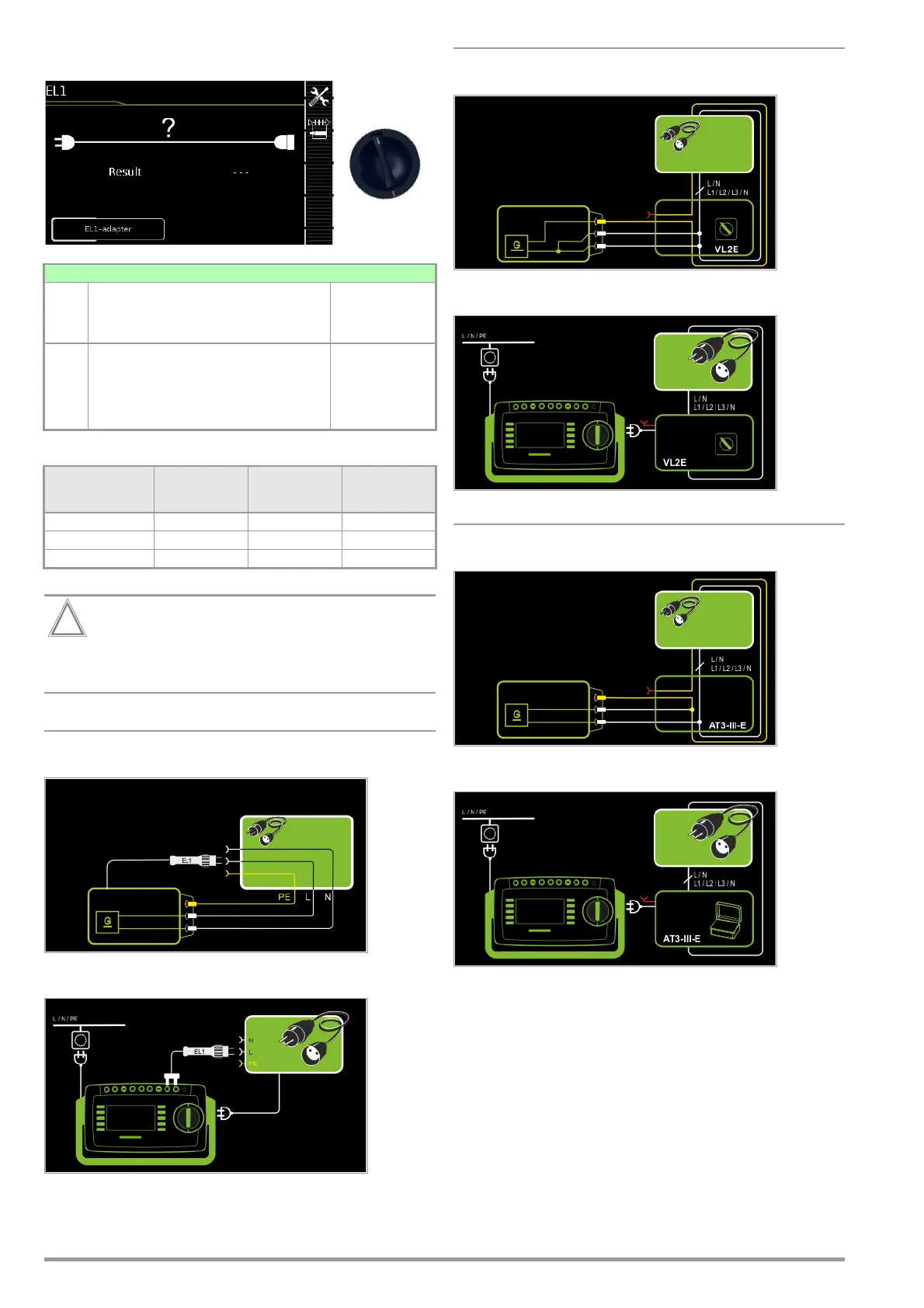
8.12 Testing Extension Cords for Correct Function – EL1
* No checking for reversed polarity takes place when the EL1 adapter is used.
This function permits an evaluation of the continuity of
the active conductors L(1, 2, 3) and N of an extension
cord. The PE conductor is not tested in this case.
Measurement at Single-Phase Extension Cords with EL1
Schematic Diagram
Wiring Diagram
Measurement at Single and 3-Phase Extension Cords with VL2E
Schematic Diagram
Wiring Diagram
Measurement at Single and 3-Phase Extension Cords with AT3-IIIE
Schematic Diagram
Wiring Diagram
Single measurements, rotary switch level: green
Switch
Position
Measuring Functions Measurement
Type, without
Mains to Test
Socket
EL1
Extension cord test
with adapter for single or 3-phase extension cords for
testing:
– Continuity
– Short-circuit
– Incorrect polarity (reversed wires *)
EL1 adapter
AT3-IIIE adapter
VL2E adapter
Testing for Continuity
L(1/2/3), N
Short-circuiting
between:
L(1/2/3), N
Polarity rever-
sal / clockwise
phase sequence
EL1 adapter
XX—
VL2E adapter
XXX
AT3-IIIE adapter
XXX

 Loading...


