GMC-I Messtechnik GmbH 27
Measurements and measurement series can only be
saved after measurement has been completed. Mea-
sured values can only be added to intermediate buffer
memory during a measurement. Customer, location and
other entries cannot be changed in the memory menu.
These have to be selected directly in the database and
entered or changed.
Please observe the following before storing tests or measure-
ments to the test instrument:
If applicable, the date of recalibration is printed on test
reports, or transmitted to a PC during when exporting
test data. For this reason we recommend checking the
recalibration date saved in the test instrument before
starting work with your new test instrument (see
page 12).
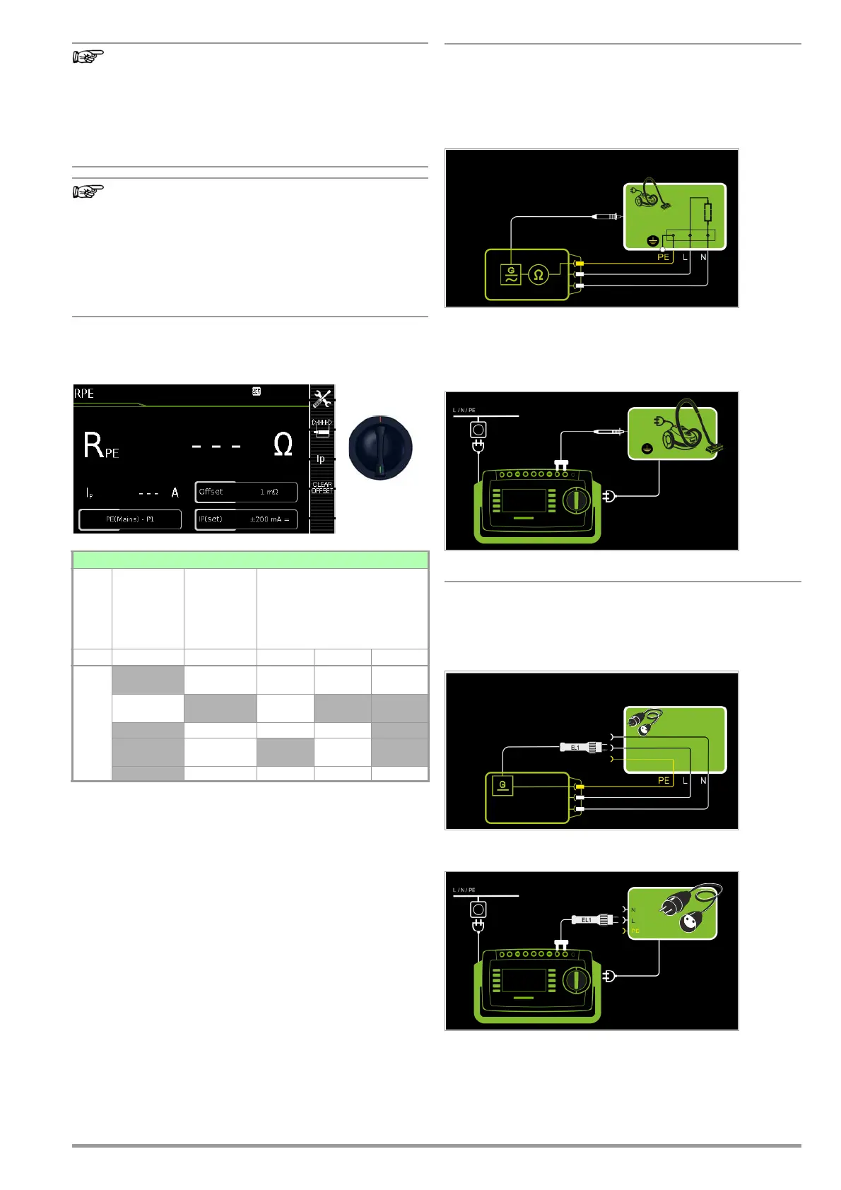
8.5 Measuring Protective Conductor Resistance – RPE
1
10/25 A-RPE measurements are only possible with line voltages of 115/230 V and
line frequencies of 50/60 Hz.
2
Connection of 2
nd
test probe for two-pole measurement with SECUTEST PRO/
SECULIFE ST BASE(25) (or instrument with feature H01)
3
Can only be selected if the IP(set) parameter has been set to 10 A~
only with SECUTEST PRO/SECULIFE ST BASE (or instrument with feature G01)
4
Can only be selected with SECUTEST BASE or if the IP(set) parameter has been set
to 200 mA.
Application, Definition, Measuring Method
Protective conductor resistance is the sum of the following resis-
tances:
• Connector cable or device connector cable resistance
• Contact resistance at plug and terminal connections
• Extension cord resistance if applicable
Protection Category I Devices
– Measurement type PE(TS) - P1 (passive)
– DUT mains plug to test socket
– Test probe P1 to P1 terminals
Schematic Diagram
Protective conductor resistance is measured between the earth-
ing contacts at the mains plug and the earthing contact con-
nected to the housing by contacting the housing with test probe
P1.
Wiring Diagram
Measurement of RPE at Single-Phase Extension Cords with EL1
– Measurement type PE(TS) - P1 (passive)
– Extension cord plug to test socket
– EL1 to P1 terminals
Schematic Diagram
Wiring Diagram
Single measurements, rotary switch level: green
Switch
Position
Measure-
ment Type,
with Mains
to Test
Socket
Measure-
ment Type,
without
Mains
to Test
Socket
Measuring Functions
R
PE
Protective conductor
resistance
Ip Test current
200 mA
10 A
1
25 A
1
R
PE
Passive:
PE(TS) - P1
•••
Active:
PE(TS) - P1
4
•
PE(mains) - P1 ••
PE(mains) - P1
clamp
3
•
P1 - P2
2
•••

 Loading...


