28 GMC-I Messtechnik GmbH
Protection Category I Devices
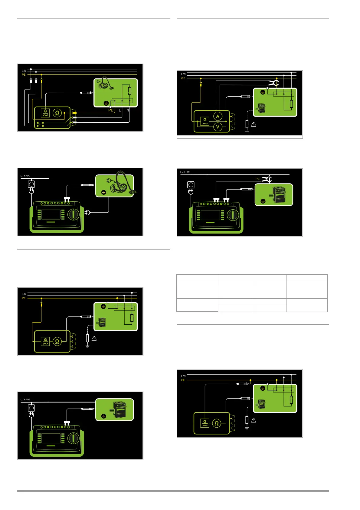
Special Case: Line Voltage at Test Socket (for testing PRCDs)
– Measurement type PE(TS) - P1 (active)
– DUT mains plug to test socket
– Test probe P1 to P1 terminals
Schematic Diagram
Protective conductor resistance is measured between the earth-
ing contacts at the mains plug and the earthing contact con-
nected to the housing by contacting the housing with test probe
P1.
Wiring Diagram
Protection Category I Devices
Special Case: Permanently Installed DUTs
– Measurement type PE(mains) - P1
– Test probe P1 to P1 terminals
Schematic Diagram
In the case of permanently installed DUTs, protective conductor resis-
tance is measured between the mains power earthing contact
and the earthing contact connected to the housing by contacting
the housing with test probe P1.
Wiring Diagram
Measurement via current clamp sensor
at permanently installed DUT
– Measurement type PE(mains) - P1 clamp
– Test probe P1 to P1 terminals
– Clamp to COM-V (only with SECUTEST PRO or feature I01
with
optional current clamp sensor)
Schematic Diagram
Measurement of test current by closing the current clamp sensor
around mains PE and contacting the housing with test probe P1
for permanently installed protection category I devices under test
Wiring Diagram
Set Measuring Range at Current Clamp Sensor and Parameter at the
SECUTEST PRO or SECULIFE ST BASE
This measurement type can only be selected if test current is set
to 10 A AC.
* Only with WZ12C
2-Pole Measurement at Permanently Installed DUTs
(only with SECUTEST PRO or feature H01)
– Measurement type P1 - P2
– Test probe P1 to P1 terminals
– Test probe P2 to P2 terminals
Schematic Diagram
PE at the mains connection is contacted with the second test
probe instead of via the test instrument’s mains plug.
SECUTEST PRO Clamp SECUTEST PRO
Transformation Ratio
Parameter
Transformation
Ratio
(switch *)
Measuring
Range
Display Range
with Clamp
1 mV : 1 mA
WZ12C
1 mV : 1 mA 1 mA ... 15 A 0 mA ... 300 A

 Loading...


