GMC-I Messtechnik GmbH 29
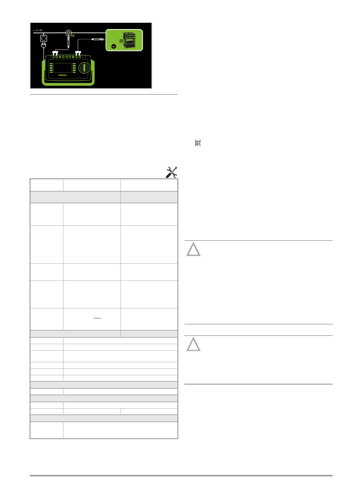
Wiring Diagram
Resistance is measured:
• Between each exposed conductive part of the housing and the
earthing contacts at the mains and the device plug (if a
removable mains connector cable is used), or the protective
conductor terminal for permanently installed devices.
• As 4-pole measurement
• Between the earthing contacts at the mains plug and the
earthing contacts at the device plug for device connector cables
• Between the earthing contacts at the mains plug and the
earthing contacts at the coupling socket for extension cords
Setting Measuring Parameters for RPE
1
Measurement cannot be performed with 10/25 A AC for this measurement type.
2
SECUTEST PRO /SECULIFE ST BASE (feature G01): This type of measurement can only
be selected if a test current of 10 A AC has been chosen.
Entering and Deleting Offset Values
The test instrument determines protective conductor resistance
by means of a 4-pole measurement. If measurement cables or
extension cords are used whose ohmic resistance should be
automatically subtracted from the measurement results, there are
two ways to save the respective offset value in the R
PE
switch
position:
• Entry via the numeric keypad
• Acceptance of the momentary measured value by pressing the
SET
OFFSET
softkey
Proceed as follows in order to accept the measured value:
➭
Start the measurement and wait until the measured value settles in.
➭ Press the
SET OFFSET
key. The value is transferred to the offset
field.
The entered or accepted offset value is permanently stored and is
subtracted from all protective conductor resistance values mea-
sured in the future. This applies to single measurements as well
as to measurements conducted in the AUTO switch positions.
The symbol is displayed in the header in all switch positions
until the offset value is deleted by pressing the CLEAR OFFSET soft-
key (R
PE
switch position).
Protective Conductor Current Measurement with 25 A AC
In accordance with IEC 60601, at least 25 A must be achieved
with a load of 0.1 Ω and a maximum voltage of 0.6 V.
Continuous protective conductor resistance measurement with a
test current of 25 A is not possible due to contact resistance at
the jacks.
If the test instrument is operated at room temperature, an uninter-
rupted test duration of at least 15 seconds is possible. Under other
conditions, maximum test duration may be shorter and/or the
measurement may be prematurely terminated.
Suitable measurement cables with a minimum cable
cross-section of 2.5 mm must be used when measuring
protective conductor resistances with a “25 A AC” test
current.
Included with the SECULIFE ST BASE25: suitable test probe
with green strain relief sleeve.
For subsequent orders, we recommend the SK2-25A
test probe (Z746C).
Under certain circumstances, the required standard val-
ues might not be complied with if unsuitable accessories
are used.
Measurement duration with a 25 A test current is limited
(see technical data).
An error message is generated if measurement duration
is exceeded which results in a temperature increase at
the test instrument.
Measuring Pa-
rameter
Meaning
Measurement Type
Suitable for
DUT Connection via
(passive:) PE(TS)
– P1
Testing is conducted between the
two protective conductor terminals:
at the test socket and test probe
P1.
Test socket, EL1 with DUT at test
socket, VL2E, AT3 adapter (AT3-
IIIE, AT3-IIS, AT3-IIS32),
AT16DI/AT32DI
Active: PE(TS) –
P1
1
Same as PE(TS) – P1, but with
line voltage to the test socket,
200 mA AC flows immediately.
A ramp-like, slowly rising DC test
current flows (PRCD triggering is
avoided) at +200 mA DC, -
200 mA DC and ±200 mA DC.
Test socket (for PRCDs)
PE(mains) – P1
Permanently con-
nected DUTs
Testing is conducted between the
ground terminal at the mains and
test probe P1.
Permanent connection
P1 – P2
SECUTEST PRO/SECULIFE ST BASE
(feature H01):
2-pole measurement between
test probes 1 and 2 (see section
6.6)
Permanent connection
Clamp
2
SECUTEST PRO
/
SECULIFE ST BASE
(features G01 and I01):
Test current measurement with
current clamp sensor
Permanent connection
IP(set)
+200 mA DC Test current: positive direct current
-200 mA DC Test current: negative direct current
±200 mA (DC) Test current: direct current whose polarity is reversed every 2 sec-
onds
200 mA (AC) Test current: alternating current, adjustable frequency f, see below
10 A (AC)
10 A test current:
SECUTEST BASE10
or
PRO
only (feature G01)
25 A (AC)
25 A test current:
SECULIFE ST BASE25
only (feature G02)
f – only at 200 mA (AC)
50 ... 200 Hz Test frequency (adjustable in steps: 50, 60, 110, 150, 200 Hz)
Offset
> 0 ... < 5 Ω Zero balancing for a selected reference point.
Clamp factor
– only for clamp measurement type
1 mV : 1 mA Transformation ratio of the WZ12C current clamp sensor.
For setting the current clamp factor at the WZ12C clamp and the
SECUTEST PRO (see table above).

 Loading...


