GMC-I Messtechnik GmbH 59
10.2 User-Defined Test Sequences / Remote Control
(only with feature KB01, “Z853R – SECUTEST DB+”)
10.2.1 General
When creating user-defined test sequences, the author of the test
sequence can define and configure individual test steps himself,
and specify the order in which they’re run.
With the help of IZYTRONIQ
PC software (as of firmware 2.1.1), test
sequences can be created at the PC and transferred to the test
instrument via a USB port.
Up to 1200 test steps can be distributed to as many as
24 test sequences and saved to memory at the test
instrument.
Similar options are available to the user when the test instrument
is remote controlled (e.g. via IZYTRONIQ IZY remote test
sequences).
Some of the test steps necessitate advance testing in the form of
inspections or test instructions, for example so that the inspector
has enough time to contact the respective location with the probe
at the point in time of test execution, or to set the DUT to the
appropriate state.
If user-created test sequences are created and/or used, or in the
case of remote control of the test instrument, the creator of the
test sequences or the user/inspector assumes responsibility for
standards-compliant test steps and execution of advance tests in
the correct order.
If you change or shorten the default test sequences
for the respective standards, the danger exists that they
will no longer be compliant and will thus become invalid
as substantiation of operating safety in accordance with
DGUV regulation 3 or BetrSichV, or will no longer fulfil
these standards.
10.2.2 Testing of Probe Connection P1 and Probe Fuse P1
If probe P1 is used in a test sequence, a “Probe Test” step with
“Probe: Probe Connection P1” must be included in the respective
test sequence. Background: In addition to assuring that a probe
is connected to probe connection P1, the probe test at connec-
tion P1 also determines whether or not the probe’s fuse link is
intact.
If the fuse at test probe P1 is defective, all subsequent
measurements using this measuring path are incorrectly
evaluated as good!
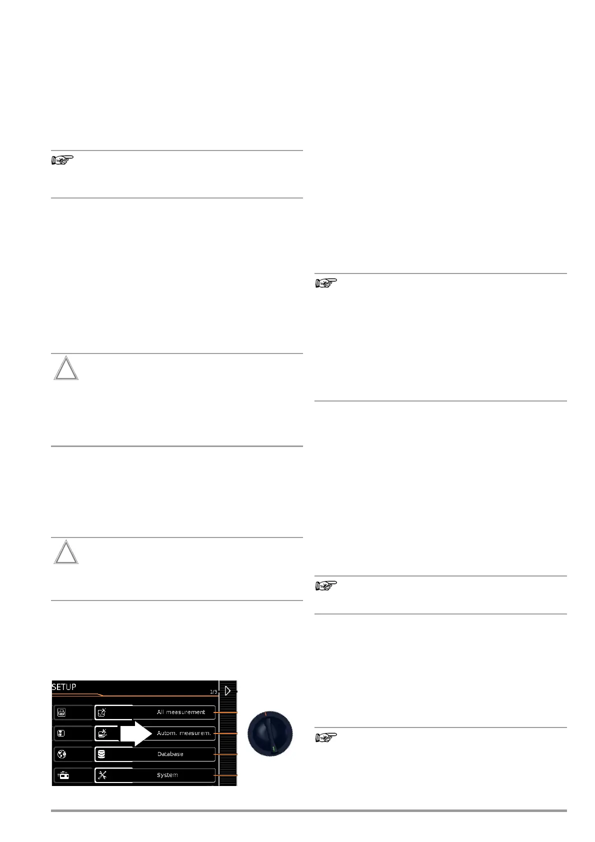
10.3 General Settings (Setup: auto measurements parameter)
The following settings can be entered for all test sequences in the
SETUP switch position on menu page 1/3 under the auto measure-
ments parameter (see section 4.3):
Automatic Measurements (1/3)
❑ At the End of the Sequence
At the end of a sequence, either the save symbol appears in
order to prompt storage (“memory screen” parameter), or the
results list (“results list” parameter) is displayed.
❑ Considering Measuring Uncertainty
If Yes is selected, measuring uncertainty is taken into consider-
ation when the measurement results are displayed. The final
result which appears at the display is downgraded by an
amount equal to measuring uncertainty.
❑ Auto Measuring Point
If Yes is selected, the test instrument detects whether or not
the protective conductor is contacted with the probe during
the protective conductor resistance measurement of an auto-
matic test sequence and automatically starts recording a new
measuring point. Statuses are indicated by various, continu-
ous acoustic signals. The protective conductor test can thus
be conducted without using the keys on the instrument.
The “Auto Measuring Point” function is only activated
during test steps of the “multiple measurement” type. If
you want to use this function ...
– In the case of integrated test sequences: Make sure
that the “multiple measurement” test parameter
(see page 54) is selected for the RPE test step.
– In the case of user-defined test sequences (only with
database extension, feature KB01, “Z853R –
SECUTEST DB+”): make sure that the RPE test step
has been entered to the sequence as a “multiple
measurement”.
Automatic Measurements (2/3)
❑ Initial Window Style
Selection can be made here between a tree view and a detail
view for the first page of the test sequence (see section 10.4).
❑ Limit Value Mode
If you want to use only the limit values specified in the stan-
dards to evaluate the measurements, set the parameter to
Normal.
When set to Expert, the LIMIT softkey appears next to the
“measurement failed” popup if the measurement has not been
passed. This key makes it possible to enter a user-defined
limit value (as a rule a limit value specified by the manufacturer
which deviates from the standard), in order to allow the test to
be passed under these new conditions.
Entry of a user defined limit value is not possible if “Con-
tinue” is selected for the “Limit Violation” option.
❑ Limit Value Violation (only with feature KD01, “Z853S – SECUTEST
DB COMFORT”)
With its “Try Again” operating mode, the test instrument makes
it possible to immediately restart the failed test step and
repeat the measurement in the event that a limit value is vio-
lated.
In the “Continue” mode, the test instrument doesn’t terminate
the test sequence in the event of a limit value of violation, and
instead continues testing despite any individual steps which
have failed.
If a limit value violation occurs during the test sequence,
the respective test step designation appears in red in the
header for all following test steps, so that it’s already

 Loading...


