42 GMC-I Messtechnik GmbH
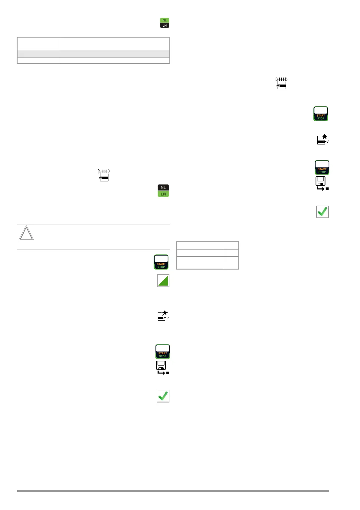
Direct Selection – Setting Polarity
– for Direct and Differential Only
Prerequisites for Touch Current Measurement
• Visual inspection has been passed.
• For protection category I devices
Protective conductor resistance testing has been passed.
• Insulation resistance testing has been passed.
Test Sequence for Direct and Differential Current Methods
➭ Before conducting any leakage current measurements, make
sure that the “Ref. voltage L-PE” and “Testingfreq. Alt” mea-
surement parameters have been correctly set in SETUP (see
section 6.2).
➭ Set the rotary switch to the I
B
position.
➭ Select measurement type Direct P1 or Differential P1:
– By setting the parameters
or
– Via the Measurement Type key
➭ In the case of direct and differential current measurement,
measurement must be performed with mains plug po-
larity in both directions. Select the respective polarity
to this end by pressing the NL/LN key.
➭
Connect the DUT’s mains plug (protection category II) to the test
instrument’s test socket.
Testing is conducted in the presence of line voltage.
➭ Start the test: press the START/STOP key.
➭ Acknowledge the warning which indicates that line
voltage will be connected to the test socket.
➭ Switch the device under test on.
➭ Contact all accessible conductive parts, one after the other,
which are not connected to the housing with test probe P1.
➭ The measured values are displayed. The measured
value recording symbol shown at the right appears.
Each time this key is pressed, the currently displayed
measured value is saved to buffer memory.
➭ Turn off the device under test.
➭ End the test: press the START/STOP key.
The save symbol appears (floppy disk showing the
number of measured values stored to buffer memory)
and prompts you to save the measured values to an ID
number.
➭ Read the measured values and compare them with the
table of permissible limit values.
➭ Press the ESC key in order to discard the measured
values stored to buffer memory and acknowledge by
pressing the key shown at the right.
Test Sequence for Alternative Measuring Method
➭ Before conducting any leakage current measurements, make
sure that the “Ref. voltage L-PE” and “Testingfreq. Alt” mea-
surement parameters have been correctly set in SETUP (see
section 6.2).
➭ Set the rotary switch to the I
B
position.
➭ Select measurement type Alternative P1
or Alternative P1–P2 (feature H01):
– By setting the parameters
or
– Directly via the Measurement Type key
➭ Connect the DUT’s mains plug (protection category II) to the
test instrument’s test socket.
➭ Start the test: press the START/STOP key.
➭ Contact all accessible conductive parts, one after the
other, which are not connected to the housing with
test probe P1.
➭ The measured values are displayed. The measured
value recording symbol shown at the right appears.
Each time this key is pressed, the currently displayed
measured value is saved to buffer memory.
➭ End the test: press the START/STOP key.
The save symbol appears (floppy disk showing the
number of measured values stored to buffer memory)
and prompts you to save the measured values to an ID
number.
➭ Read the measured values and compare them with the
table of permissible limit values.
➭ Press the ESC key in order to discard the measured
values stored to buffer memory and acknowledge by
pressing the key shown at the right.
Maximum Permissible Limit Values for Leakage Current in mA
Key
I
T
Touch current (leakage current from welding current)
Measuring
Parameter
Meaning
Measurement Type
L/N or N/L Selection of polarity for mains voltage to the test socket
Test Standard I
T
VDE 0701-0702:2008 0.5
DIN EN 60974-4
VDE 0544-4:2017-05
10 mA

 Loading...


