GMC-I Messtechnik GmbH 45
Setting Measuring Parameters for IE
1
Measurement must be performed with mains polarity in both directions. The larg-
est value is documented
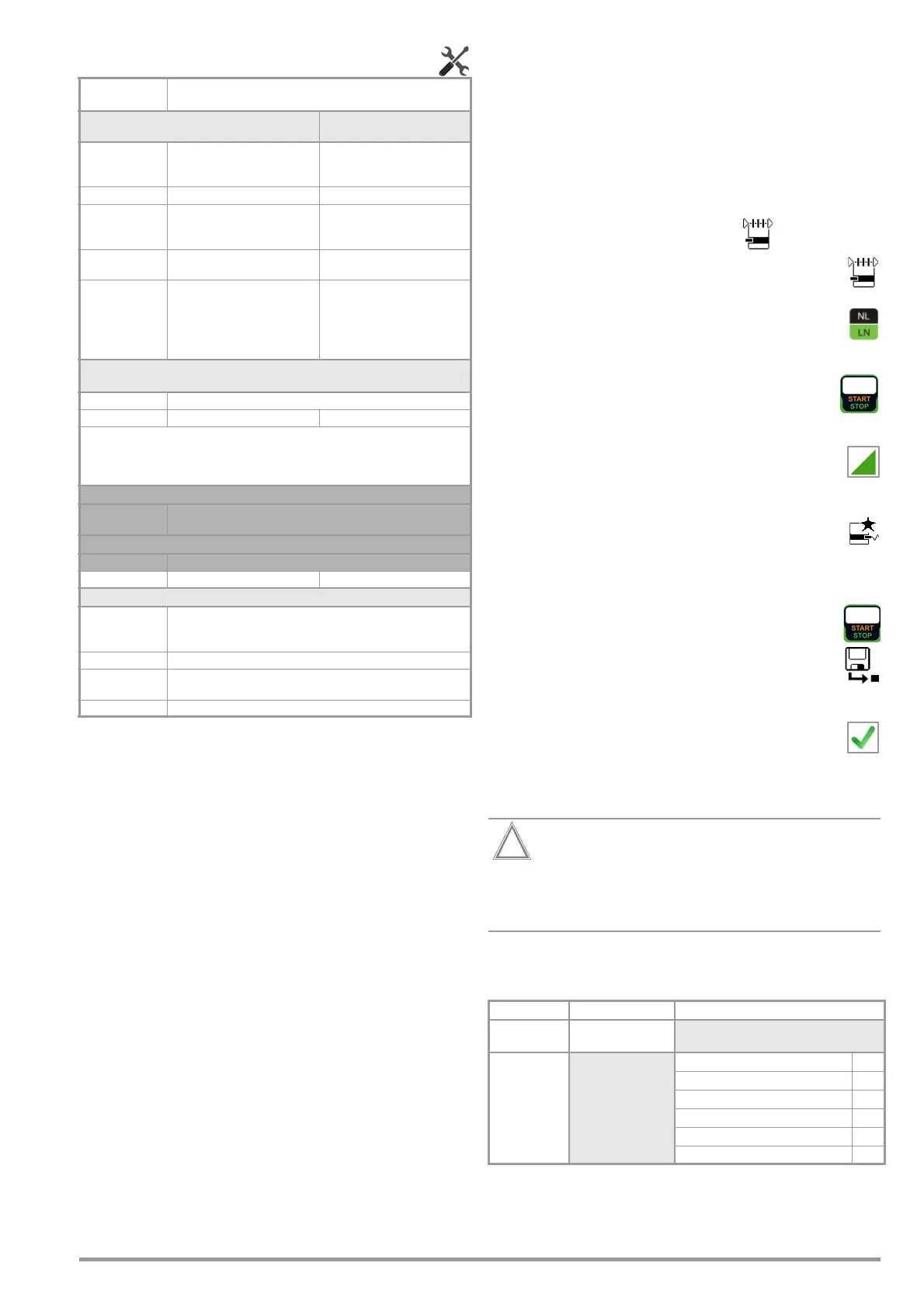
Test Sequence
➭ Before conducting any leakage current measurements, make
sure that the “Ref. voltage L-PE” and “Testingfreq. Alt” mea-
surement parameters have been correctly set in SETUP (see
section 6.2).
➭ Set the rotary switch to the I
G
position.
➭ Connect the DUT in accordance with the selected measuring
method.
➭ Select the measurement type:
– By setting the parameters
or
– Directly via the Measurement Type key
➭ As an alternative, you can select the measurement type
directly using the key shown at the right.
➭ In the case of direct and differential current measurement,
measurement must be performed with mains plug po-
larity in both directions. Select the respective polarity
to this end by pressing the NL/LN key.
➭ Start the test: press the START/STOP key.
➭ After each reconnection to the mains, and as soon as
the first test is started, a mains connection test is exe-
cuted.
➭ In the case of the direct or differential measurement type:
Acknowledge the warning which indicates that line
voltage will be connected to the test socket.
➭ Switch the device under test on.
➭ The measured values are displayed. The measured
value recording symbol shown at the right appears.
Each time this key is pressed, the currently displayed
measured value is saved to buffer memory.
➭ Turn off the device under test.
➭ End the test: press the START/STOP key.
The save symbol appears (floppy disk showing the
number of measured values stored to buffer memory)
and prompts you to save the measured values to an ID
number.
➭ Read the measured values and compare them with the
table of permissible limit values.
➭ Press the ESC key in order to discard the measured
values stored to buffer memory and acknowledge by
pressing the key shown at the right.
Test Sequence with AT3-IIIE Adapter
Please observe the operating instructions for the AT3-
IIIE regarding correct connection of the test adapter and
the device under test, as well as peculiarities involved in
the test sequence.
Maximum Permissible Limit Values for Equivalent Leakage
Current in mA
I
GA
Device leakage current
I
EA
Equivalent leakage current
PE Protective conductor
1
For devices with heating power ≥ 3.5 kW
2
This limit value is not taken into consideration in the DIN EN 62353
(VDE 0751-1) standard.
Measuring
Parameter
Meaning
Measurement Type
Suitable for
DUT Connection via
Direct
Direct measuring method, optional
probe contact
Test socket,
AT16DI/AT32DI
(only diff. is sensible)
Differential Differential current measurement Test socket
Alternative Equivalent leakage current mea-
suring method with probe con-
tact
Test socket, AT16DI/AT32DI
AT3 adapter
SECUTEST PRO or feature I01:
measurement with
AT3 adapter
AT3-IIIE, AT3-IIS, AT3-IIS32
Clamp
SECUTEST PRO
or feature I01:
Measurement of device leakage
current via current clamp sensor
with voltage output, and conver-
sion to and display as current
values.
Permanent connection
Polarity
1
– for direct, differential and AT3 adapter measurement types
only
L/N or N/L Selection of polarity for mains voltage to the test socket
The U (setpoint) and frequency (setpoint) measuring parameters for the “Alterna-
tive” measurement type are no longer included as of firmware version 1.7.0.
These parameters apply to individual measurements as well as test sequences
and have to be entered in SETUP (see section section 6.2).
U(set) – for alternative measurement type only
110 V, 115 V,
220 V, 230 V, 240 V
Selection of a line voltage for synthetic test voltage
Frequency(set) – for alternative measurement type only
48 Hz ... 400 Hz
Selection of a line frequency for synthetic test voltage
Clamp factor – only for clamp measurement type
1 mV : 1 mA Transformation ratio of the WZ12C current clamp sensor.
For setting the current clamp factor at the WZ12C clamp and the
SECUTEST PRO (see table above).
10 mV : 1 mA
100 mV:1 mA Transformation ratio of the SECUTEST CLIP current clamp sensor.
For setting the current clamp factor at the SECUTEST PRO.
1 V : 1 A
Test Standard I
GA
I
EDL
VDE 0701-0702
PC I: 3.5 / 1 mA/kW
1
PC II: 0.5
IEC 62353
(VDE 0751-1)
PC II
0.2
2
PC I (PE or parts connected to PE)
1
Permanently connected devices with PE
10
Portable x-ray devices with additional PE
5
Portable x-ray devices without additional PE
2
Devices with mineral insulation
5

 Loading...


