

J
Jamie PowellSep 23, 2025
What does tx Con'd mean on GSE Scales?
- FfcarpenterSep 23, 2025
The 'tx Con'd' message on GSE Scales appears briefly when the handshake is re-asserted after the tx on hold message occurs.
What does tx Con'd mean on GSE Scales?
The 'tx Con'd' message on GSE Scales appears briefly when the handshake is re-asserted after the tx on hold message occurs.
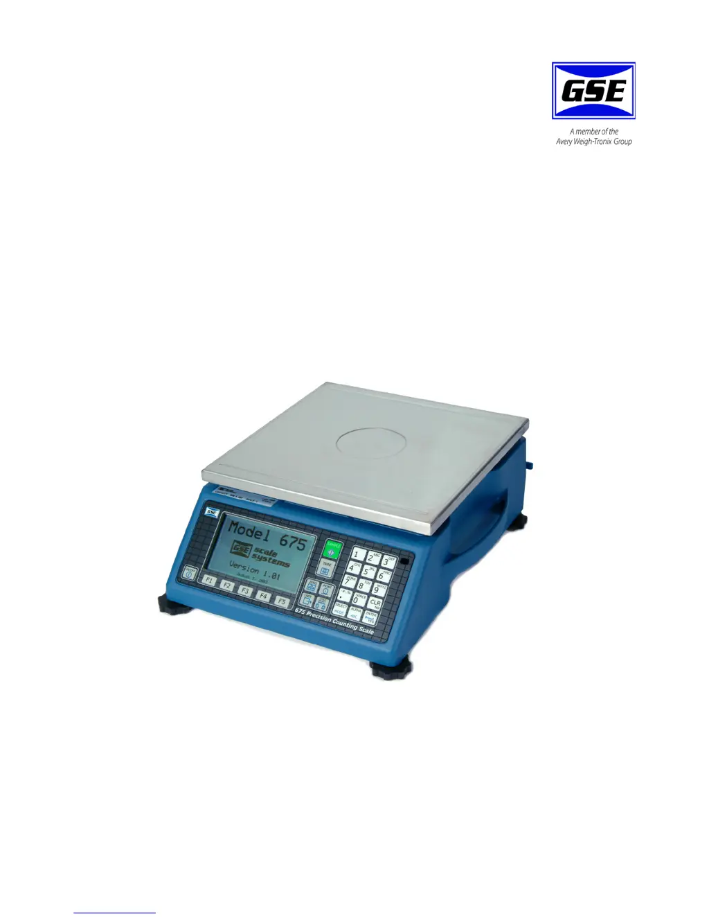
What does 'CoDE07 Tare< 0!' mean on my GSE 675 Scales?
The 'CoDE07 Tare< 0!' error on your GSE Scales indicates a negative tare was attempted but is not allowed. For auto-tares, the GROSS Weight must be greater than zero unless P162 is changed to allow negative tares.
What does 'CoDE81 Macro Stack' mean on GSE Scales?
This error indicates that the maximum number of macros pushed onto the stack has been exceeded. This usually means that macros are being invoked faster than they can be executed.
What does CoDE12 No Mods! mean on GSE Scales?
The 'CoDE12 No Mods!' error on GSE Scales indicates that accessing Setup Mode is being prevented.
What does Must Free mean on GSE Scales?
The 'Must Free' error on GSE Scales indicates that a serial or database start collection command (S%’ or S%*) was issued without first freeing memory with the F%’ or F%* command.
What should I do if my GSE 675 display 'CoDE95 SyErr HSR00'?
The 'CoDE95 SyErr HSR00' error on your GSE Scales indicates an error occurred at startup or during operation. Contact GSE.
What does 'tx abort' mean on my GSE 675?
The 'tx abort' message on your GSE Scales occurs if the key is pressed when the tx on hold error message is shown, or if P209 is set for abort and the transmit buffer becomes full.
How to troubleshoot CoDE85 Syntx Error on GSE Scales?
To troubleshoot a 'CoDE85 Syntx Error' on GSE Scales, re-check the macro or analyze the macro debug table to find out where the error occurred.
How to fix Cksum error on GSE Scales?
To fix a 'Cksum error' on GSE Scales, re-flash the indicator.
What to do if GSE 675 display 'Code02 Under Load!'?
If the 'Code02 Under Load!' error appears on your GSE Scales, it could be due to excessive loading, in which case you should reduce the load. Otherwise, check the load cell connections. If a 4 wire load cell cable is being used, check that the sense jumpers are in place. Also, verify that the capacity selection P110 is correct; use the information parameters, especially P61103 and P61104, to check the setup and input signal.
Details the structure and purpose of the user manual.
Explains the formatting used for keystrokes and displayed messages.
Defines signal words and symbols for hazards and important notes.
Guidelines for connecting pluggable equipment to accessible sockets.
Specifies isolator requirements for permanently wired connections.
Instructions for safe handling and replacement of batteries to prevent explosion.
Advises against installing the unit near water as it is not a washdown unit.
Details DB9 connector pin assignments for connecting a remote scale.
Instructions for enabling and setting up the Quick Count application.
Details how to store and recall part numbers with average piece weight.
Explains how to access setup menus for the APW Lookup application.
Instructions for using the Quick Count method for parts counting.
Steps for sampling and counting parts using the APW Lookup.
Using the keypad for simple sample and count operations.
Important considerations and tips for performing calibration.
How to enter the calibration mode from the application menus.
Specific steps to access calibration from APW Lookup or Quick Count.
Introduction to the various calibration methods available.
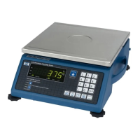
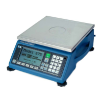
Descriptions and remedies for operational errors like Under Load and Zero Max.