EasyManua.ls Logo

GSE 675 - User Manual

GSE 675
48 pages
Print Icon
To Next Page IconTo Next Page
Loading...
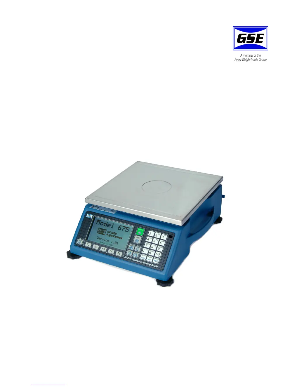
Model 675
Precision Parts Counter
User Instructions
39-10-40879 Issue AI September 2010

Other manuals for GSE 675

Questions and Answers

  • M
    Marilyn LeeAug 26, 2025
    What does 'CoDE05 Zero> Max.!' mean on GSE Scales and how can I resolve it?
    • H
      haroldsimonAug 26, 2025
      The 'CoDE05 Zero> Max.!' error on GSE Scales means an attempt was made to zero out more than allowed per P118 selection. Use the key for subtracting off container weights, or if a large dead-load is always to be present, apply this dead-load during the 'No Load?' prompt during calibration to permanently eliminate the offset.
  • C
    Cheyenne ParksAug 26, 2025
    How to fix 'Cksum error' on GSE Scales?
    • S
      Stephen SmithAug 26, 2025
      A 'Cksum error' indicates a problem with the integrity of its firmware. To fix this, re-flash the indicator.
  • E
    Elizabeth RiceAug 25, 2025
    What does 'CoDE03 Over- Load!' mean on GSE 675 Scales and how to fix it?
    • D
      Denise WolfeAug 26, 2025
      The 'CoDE03 Over- Load!' error on your GSE Scales means the input signal is greater than positive full scale. Use the same checks as for an underload situation.
  • A
    Anthony WilsonAug 25, 2025
    What to do if GSE 675 display 'Code02 Under Load!'?
    • J
      Joseph DavisAug 26, 2025
      If the 'Code02 Under Load!' error appears on your GSE Scales, it could be due to excessive loading, in which case you should reduce the load. Otherwise, check the load cell connections. If a 4 wire load cell cable is being used, check that the sense jumpers are in place. Also, verify that the capacity selection P110 is correct; use the information parameters, especially P61103 and P61104, to check the setup and input signal.
  • J
    Joseph HernandezAug 25, 2025
    Why do my GSE Scales show 'CoDE11 WRONG CODE!'?
    • J
      jennifer13Aug 25, 2025
      This error indicates that the incorrect access code was entered, thus preventing changes. To resolve this, enter the proper code or press the key alone to view selections without making changes.
  • O
    obriencandiceSep 4, 2025
    What does 'CoDE99 Can't Set!' mean on my GSE 675?
    • M
      maymelanieSep 4, 2025
      The 'CoDE99 Can't Set!' message on your GSE Scales appears when you attempt to enter a value for a parameter that is not field changeable.
  • S
    Spencer MezaSep 7, 2025
    What to do if my GSE Scales show Code02 Under Load?
    • R
      Robert DuncanSep 8, 2025
      If your GSE Scales display the 'Code02 Under Load!' error, it indicates excessive loading. Reduce the load on the scale. Also, check the load cell connections. If using a 4-wire load cell cable, ensure the sense jumpers are in place and verify that the capacity selection P110 is correct. Use parameters P61103 and P61104 to check the setup and input signal.
  • M
    Mark HarrisonSep 7, 2025
    What does 'tx abort' mean on my GSE 675?
    • V
      Victoria GarciaSep 7, 2025
      The 'tx abort' message on your GSE Scales occurs if the key is pressed when the tx on hold error message is shown, or if P209 is set for abort and the transmit buffer becomes full.
  • B
    Briana RobinsonSep 7, 2025
    What does 'tx on hold' mean on my GSE 675 Scales?
    • J
      joshualewisSep 7, 2025
      The 'tx on hold' message on your GSE Scales occurs if a data transmission is held up for two seconds or more due to a deasserted handshake. Refer to the description of parameter P209 for more information.
  • A
    Ashley BakerSep 6, 2025
    What does 'NoTxX Allow' mean on my GSE 675 Scales?
    • J
      Justin OsborneSep 6, 2025
      The 'NoTxX Allow' message on your GSE Scales, associated with Modbus, indicates that a transmission out the specified port was attempted.

Summary

General Information and Warnings

About this Manual

Details the structure and purpose of the user manual.

Text Conventions

Explains the formatting used for keystrokes and displayed messages.

Special Messages

Defines signal words and symbols for hazards and important notes.

Installation Guide

Enclosure Description

Electrical Installation Safety

Pluggable Equipment Installation

Guidelines for connecting pluggable equipment to accessible sockets.

Permanently Wired Equipment Requirements

Specifies isolator requirements for permanently wired connections.

Battery Handling and Safety

Instructions for safe handling and replacement of batteries to prevent explosion.

Installation in Wet Conditions

Advises against installing the unit near water as it is not a washdown unit.

Routine Maintenance Procedures

Cleaning the Scale

User Training Requirements

Sharp Object Usage Warning

Scale Display Overview

Keypad Layout and Features

Keypad Functions Explained

Alpha Entry Mode

Rear Panel Connections

Remote Scale Connections

Details DB9 connector pin assignments for connecting a remote scale.

Communication Port Pinouts

Remote Key Input Setup

FCC and EMC Compliance

Configuration Options

Quick Count Mode Setup

Instructions for enabling and setting up the Quick Count application.

Quick Count Setup Menu

Setup Menu Parameters

Advanced Setup Menu Navigation

Advanced Setup Menu Options

GSE Custom Applications

APW Lookup Functionality

Details how to store and recall part numbers with average piece weight.

APW Lookup Setup

Explains how to access setup menus for the APW Lookup application.

APW Lookup Setup Parameters

Setup Menu Navigation

Calibration Access

Display Style Customization

Set Modes for Operation

Advanced Setup Menu Guide

GSE Factory Default Reset

Scale Operation Guide

Quick Count Operation

Instructions for using the Quick Count method for parts counting.

Sample and Count Procedure

Accumulate Functionality

APW Lookup Operation

APW Sample and Count

Steps for sampling and counting parts using the APW Lookup.

Accumulate Function Details

GSE Default Reset Procedure

Simple Keypad Sample

Using the keypad for simple sample and count operations.

Calibration Procedures

General Calibration Notes

Important considerations and tips for performing calibration.

Accessing Calibration Mode

How to enter the calibration mode from the application menus.

Calibration Access from APW;Quick Count

Specific steps to access calibration from APW Lookup or Quick Count.

Overview of Calibration Methods

Introduction to the various calibration methods available.

New Zero Calibration

Last Zero Calibration

Temporary Zero Calibration

Only Zero Calibration

Calibration Reset Procedure

Known Loadcell Output Calibration

Multi-Scale Calibration

Troubleshooting Guide

Operational Error Codes

Descriptions and remedies for operational errors like Under Load and Zero Max.

Hardware Error Codes

ICalibration Error Codes

General Error Codes

Miscellaneous Error Codes

Communication Error Codes

GSE 675 Specifications

General IconGeneral
BrandGSE
Model675
CategoryScales
LanguageEnglish

Related product manuals