2 General Information
Topics Covered in this Chapter
▪ Sweep Offerings and Sweep Arm Details
▪ Bolt Torque Specifications
▪ Auxiliary Intermediate Well
Sweep Offerings and Sweep Arm Details
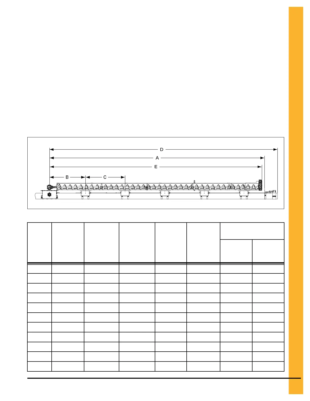
Figure 2-1 Sweep details
Table 2-1 Details for 10"
Bin
Diameter
# of
Intermediate
Wells
Distance from
Center of Bin
to Wall (A)
Distance
between
Center Well
Gate and First
Intermediate
Well (B)
Distance
between
Intermediate
Wells (C)
Distance
from Center
of Bin to
Tube End (D)
Distance between Center
of Bin to End of Sweep (E)
Maximum Minimum
24' 2 11' - 11-1/4" 66" 42" 14' - 5-3/16" 11' - 6-1/2" 10' - 9-1/2"
27' 2 13' - 5-3/16" 66" 60" 15' - 11-3/16" 13' - 1/2" 12' - 3-1/2"
30' 2 14' - 11-1/2" 78" 72" 17' - 5-13/16" 14' - 7-1/16" 13' - 10-1/16"
33' 3 16' - 5-1/2" 54" 48" 18' - 11-1/2" 16' - 1-1/16" 15' - 4-1/16"
36' 3 17' - 11-3/8" 54" 60" 20' - 5-5/8" 17' - 6-9/16" 16' - 9-9/16"
42' 4 20' - 11-3/16 54" 54" 23' - 5-7/16" 20' - 6-1/16" 19' - 9-1/16"
48' 4 23' - 11" 60" 62" 26' - 5-1/4" 23' - 6-1/16" 22' - 9-1/16"
54' 4 26' - 10-13/16" 60" 66" 29' - 5-1/16" 26' - 6-1/16" 25' - 9-1/16"
60' 5
29' - 10-5/8" 60" 66" 32' - 4-7/8" 29' - 6-1/16" 28' - 9-1/16"
66' 6 35' - 10-1/2" 48" 60" 35' - 4-3/4" 32' - 6-1/16" 31' - 9-1/16"
72' 6 35' - 10-5/16" 48" 60" 38' - 4-9/16" 35' - 5-1/16" 34' - 8-1/16"
PNEG-2308 Chain Loop Power Sweep
13