Chapter 3: Installation
Assembling the Drive Head
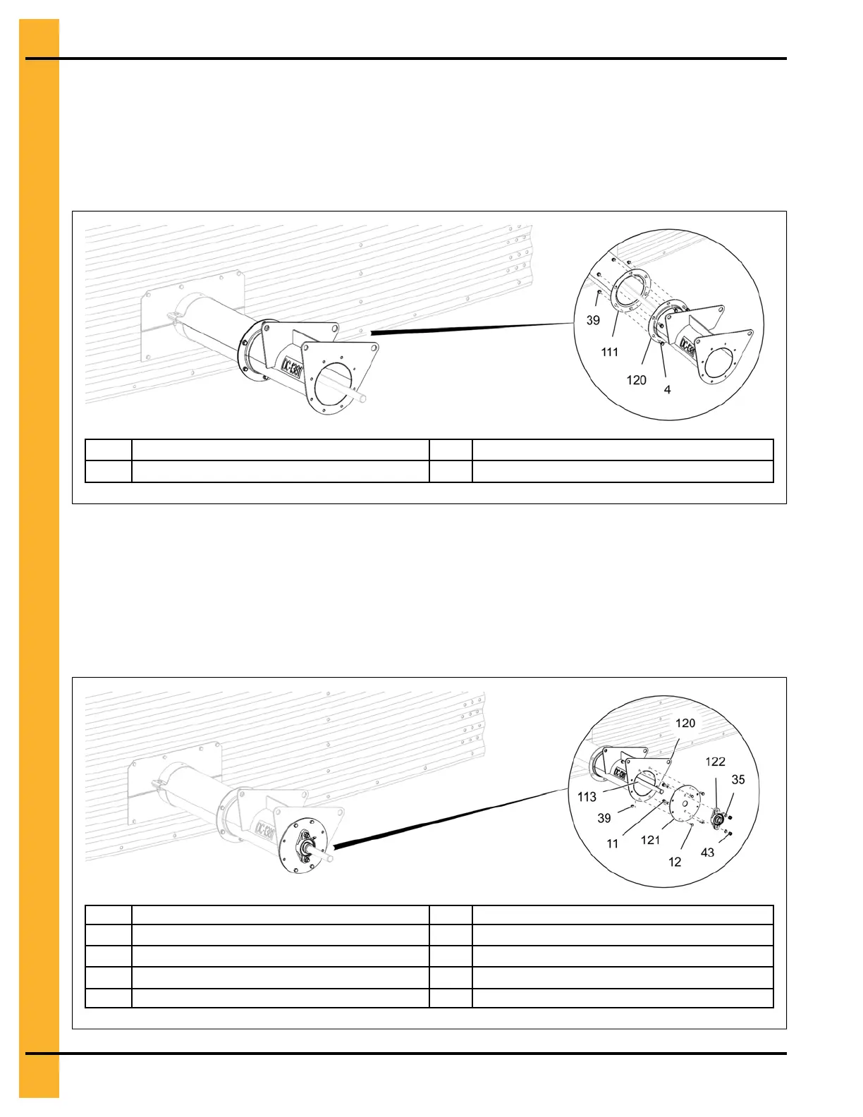
1. Align the flange of the power tube (111) with the flange of the drive tube assembly (120) and install
using 5/16" x 3/4" flange bolts (4) and 5/16" flange nuts (39).
Figure 3-48 Attaching the power tube assembly to the drive head tube assembly
4
5/16" x 3/4" flange bolt
111 Power tube
39
5/16" flange nut
120
Discharge tube assembly
2. Install the bearing (122) to the bearing plate (121) using 7/16" x 1-1/2" HHCS bolts (11), 7/16" lock
washers (35) and 7/16" hex nuts (43).
3. Slide the bearing plate assembly over the drive shaft (113) and attach it to the motor end of the tube
assembly (120) using four 5/16" x 1" HHCS bolt (12) and four 5/16" flange nuts (39) as shown.
Figure 3-49 Assembling the bearing and bearing plate to the drive head tube
11 7/16" x 1-1/2" HHCS bolt 113 Drive shaft
12 5/16" x 1" HHCS bolt 120
Discharge tube assembly
35 7/16" lock washer 121
Bearing plate
39
5/16" flange nut
122
Bearing
43 7/16" hex nut
50
PNEG-2308 Chain Loop Power Sweep