Chapter 3: Installation
Installing the Bin Flange for Unload Tube
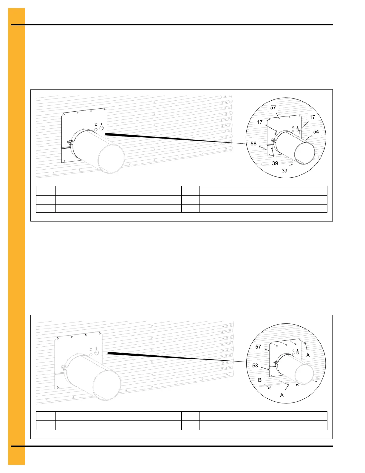
1. Attach the upper bin flange (57) and lower bin flange (58) loosely to the unload tube (54) using
5/16" x 1-1/2" HHCS bolts (17) and 5/16" flange nuts (39).
Figure 3-4 Installing the upper and lower bin flanges (gate side)
17 5/16" x 1-1/2" HHCS bolt
57
Upper bin flange
39
5/16" flange nut
58
Lower bin flange
54 Unload tube
2. Make sure that the bin wall opening is large enough for the well control rods to pass through the bin
wall before connecting the flange to the bin wall.
3. Slide the bin flanges flush up to the bin wall and tighten the bolts connecting the two flanges.
4. Drill the holes in the bin wall through the four holes located in the upper bin flange (57) and two
holes located in lower bin flange (58) and secure the bin flanges to the bin wall using six standard
bin bolts (A) and flange nuts (B).
Figure 3-5 Secure the upper and lower bin flanges (gate side)
A Standard bin bolt
57
Upper bin flange
B
Flange nut
58
Lower bin flange
20
PNEG-2308 Chain Loop Power Sweep