Chapter 3: Installation
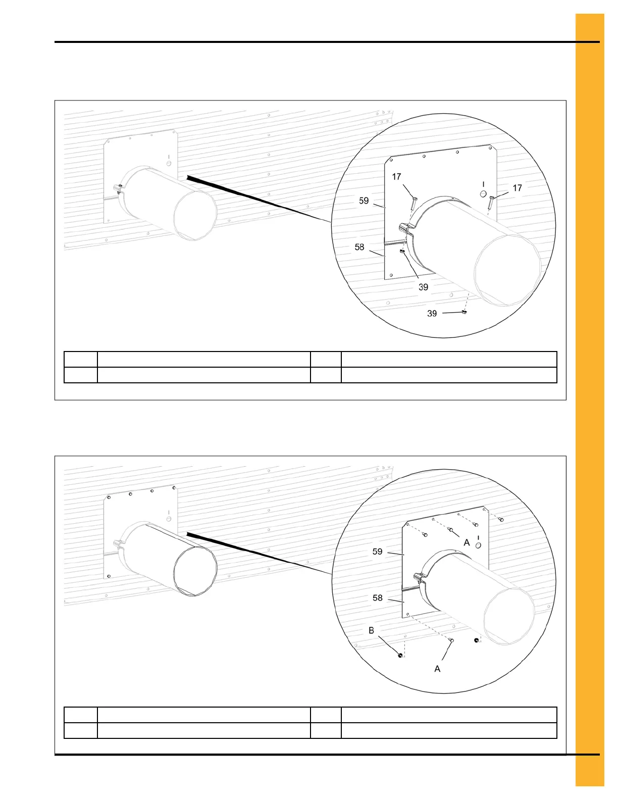
NOTE: Follow the steps from 1-4 to install the upper bin flange (59) and lower bin flange (58) to the
opposite side of the bin.
Figure 3-6 Installing the upper and lower bin flanges (opposite side)
17 5/16" x 1-1/2" HHCS bolt 58
Lower bin flange
39
5/16" flange nut
59
Upper bin flange
Figure 3-7 Secure the upper and lower bin flanges (opposite side)
A Standard bin bolt 58
Lower bin flange
B
Flange nut
59
Upper bin flange
PNEG-2308 Chain Loop Power Sweep
21
 Loading...