Chapter 3: Installation
Installing the Power Tube
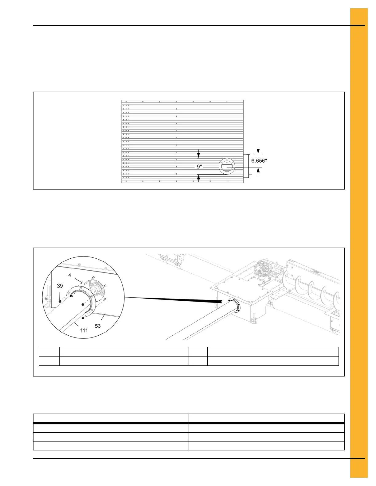
1. Mark the location for the power tube in the bin wall and cut an opening for the power tube to pass
through.
Figure 3-42 Sidewall opening details (power tube)
2. Insert the power tube (111) through the hole in the bin wall and align the tube flange with the outside
of the center well (53).
3. Secure the power tube (111) to the center well (53) using 5/16" x 3/4" flange bolts (4) and 5/16"
flange nuts (39).
Figure 3-43 Secure the power tube to the center well
4
5/16" x 3/4" flange bolt
53 Center well
39
5/16" flange nut
111 Power tube
The chart shows the minimum number of supports that should be placed beneath the span of tubing.
Even though the smaller diameter bins may not require any supports, it is always a good idea to have at
least one support positioned in the center of these shorter spans.
Bin diameter
Minimum No. of Supports
24'-42' 1
48'-60' 2
66'-72' 3
PNEG-2308 Chain Loop Power Sweep
47