Chapter 3: Installation
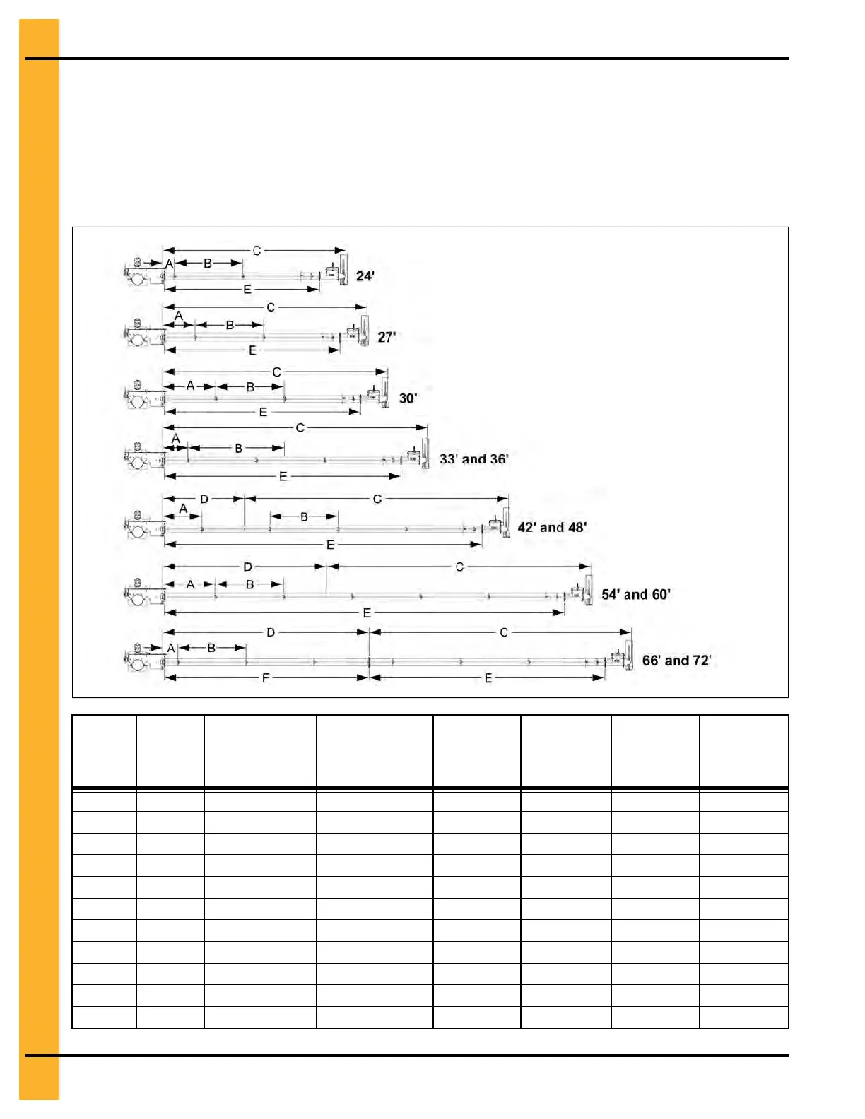
Drive Assembly and Power Tube Layout
The drive shaft and its housing tube can now be assembled. On bin diameters of 48 ft. through 72 ft.
there will be two sections of drive shafts. On bin diameters of 66 ft. and 72 ft. there will be two housing
tubes that will be joined together. Lay the sections of housing tubes and drive shafts in an open area and
using the chart and illustration below, determine the proper order of each prior to actual placement in the
bin.
Figure 3-41 Drive assembly and power tube layout
Bin
diameter
# of
bearings
Distance from
drive coupler to
first bearing (A)
Distance
between support
bearings (B)
Power shaft
length (C)
Power shaft
extension
length (D)
Power
housing
tube length
(E)
Power
housing
tube length
(F)
24' 3 10-5/8" 60" 13' - 4-5/8"
-
11' - 4"
-
27' 3 2' - 4-5/8" 60" 14' - 10-5/8"
-
12' - 10"
-
30' 3 3' - 10-5/8" 60" 16' - 4-5/8"
-
14' - 4"
-
33' 4 4-5/8" 60" 17' - 10-5/8"
-
15' - 10"
-
36' 4 1' - 10-5/8" 60" 19' - 4-5/8"
-
17' - 4"
-
42' 4 4' - 10-5/8" 60" 19' - 4-5/8" 3' 20' - 4"
-
48' 5
2' - 10-5/8" 60" 19' - 4-5/8" 6' 23' - 4"
-
54' 6 10-5/8" 60" 19' - 4-5/8" 9' 26' - 4"
-
60' 6 3' - 10-5/8" 60" 19' - 4-5/8" 12' 29' - 4"
-
66' 7 1' - 1-3/4" 60" 19' - 4-5/8" 15' - 7/16" 17' - 4" 15' - 3/8"
72' 7 4' - 1-3/4" 60" 19' - 4-5/8" 18' - 7/16" 17' - 4" 15' - 3/8"
46
PNEG-2308 Chain Loop Power Sweep