Chapter 3: Installation
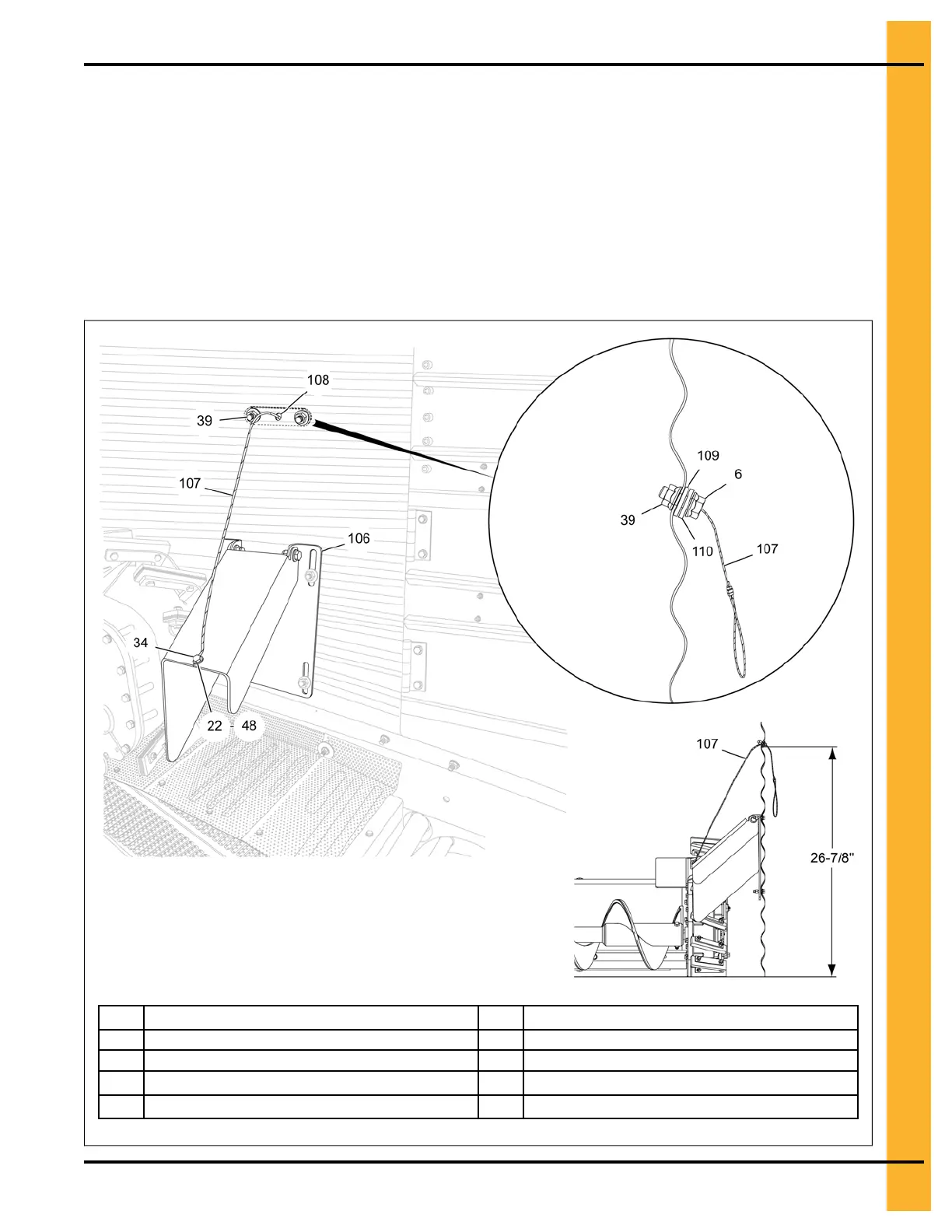
2. Measure approximately 26-7/8" from the bin floor and field drill a 1/2" hole (108) in the sidewall.
Pass the free end of the cable (107) from the outside of the bin (make sure cable wall plates (109
and 110) are pre-assembled to the cable) and attach it to the sweep stop assembly (106) using a
1/4" x 3/4" HHCS bolt (22), two 1/4" flat washers (34) and 1/4" nylock nut (48).
3. Using the wall plates as template, field drill two 3/8" holes (with reference to the 1/2" hole) and install
the cable wall plates (109 and 110) from outside the bin using 5/16" x 1" flange bolts (6) and 5/16"
flange nuts (39).
NOTE: Exact location of the cable bracket position may vary depending on the floor type, floor
height, and bin corrugation. The measurement value shown here is only approximate.
Figure 3-40 Connecting the cable to the sweep stop
6 5/16" x 1" flange bolt 106 Sweep stop assembly
22
1/4" x 3/4" HHCS bolt
107
Cable
34 1/4" flat washer 108 1/2" field drilled hole
39
5/16" flange nut
109
Sweep stop cable UHMW wall plate
48
1/4" nylock nut
110
Sweep stop cable wall plate
PNEG-2308 Chain Loop Power Sweep
45