Chapter 3: Installation
After You Finish
Make sure the gate operates smoothly and closes completely. Make any necessary adjustments.
Installing the Intermediate Well Gate
What You Should Know
• The auxiliary well control rod with smaller diameter is assembled as rod-in-rod with the larger
diameter intermediate well control rod.
• The rack and pinion assembly can only be installed after the control rods are slid into the wells. With
the rack and pinion installed, the control rods can be marked for cutting them to the appropriate
length and drilling the holes for the attachment to the well gates.
• The intermediate well and the auxiliary well control rods will only have pre-drilled holes for installing
the rack and pinion assembly. The holes to connect with the well gates need to be field drilled.
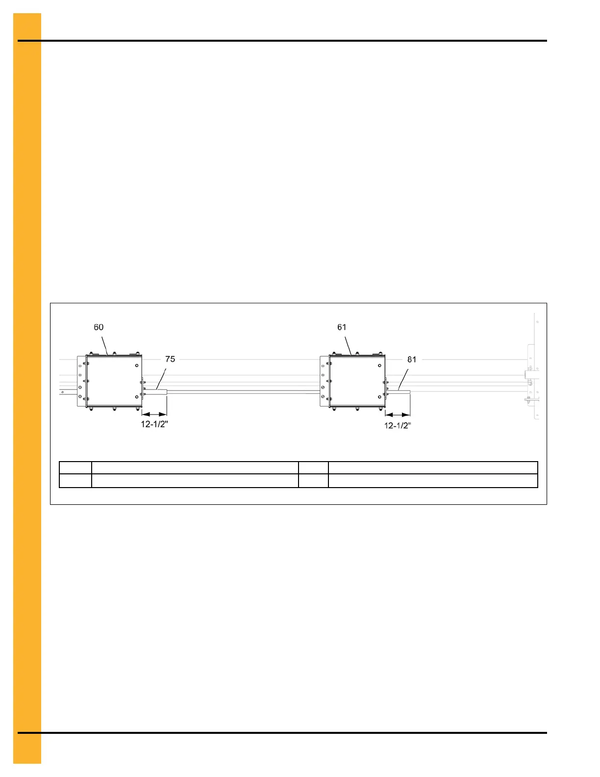
• Measure 12-1/2" from the back of auxiliary intermediate well (61) and cut the auxiliary well control
rod (81). Similarly measure 12-1/2" from the back of the last intermediate well (60) (that the rod will
control) and cut the intermediate well control rod (75) as shown below.
Figure 3-11 Cutting the control rods
60 Intermediate well 75 Intermediate well control rod
61
Auxiliary intermediate well
81
Auxiliary well control rod
1. Insert the auxiliary well control rod (81) into the intermediate well control rod (75).
2. Slide the intermediate well control rod (75) (with auxiliary control rod (81) inserted) through the holes
marked with ‘I’ on the bin flange and through the intermediate wells, until it reaches the last
intermediate well (60) from the bin flange.
NOTE: Make sure the auxiliary well control rod (81) alone slides into the auxiliary well (61) and the
intermediate well control rod (75) stops before it. Refer to Auxiliary Intermediate Well, page
15 for details.
3. Close the auxiliary well gate (116) and intermediate well gates (70) completely.
4. Align the auxiliary well control rod (81) between the holes in the auxiliary well gate (116) and attach
the control rod clamp (67) to the auxiliary well control rod (81) by inserting a 5/16" x 1-3/4" roll pin
(68) through the clamps and the field drilled hole in the control rod.
24
PNEG-2308 Chain Loop Power Sweep