Chapter 3: Installation
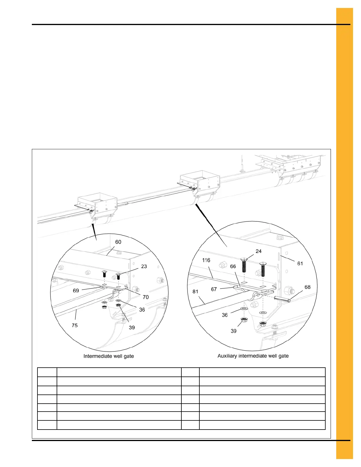
5. Secure the control rod clamp (67) along with a control rod spacer (66) to the bottom of the auxiliary
well gate (116) by using 5/16" x 1-1/4" carriage bolts (24), 5/16" flat washers (36) and 5/16" flange
nuts (39).
6. Align the intermediate well control rod (75) between the holes in the well gate (70) and attach the
control rod clamp (69) to the well gate (70) using 5/16" x 3/4" carriage bolts (23), 5/16" flat washers
(36) and 5/16" flange nuts (39).
NOTE: Repeat step 6 to connect the intermediate well control rod (75) to all the intermediate wells.
IMPORTANT: The opposite side to the center well gate opening will not receive a auxiliary
intermediate well (61) and all the intermediate wells (60) on this side will be
connected using a smaller diameter control rod (similar to auxiliary well control rod).
Follow steps 4 and 5 to connect the control rod with the intermediate wells on this
side.
Figure 3-12 Intermediate well gate assembly
23
5/16" x 3/4" carriage bolt
67
Auxiliary well control rod clamp
24
5/16" x 1-1/4" carriage bolt
68
5/16" x 1-3/4" roll pin
36 5/16" flat washer 69
Intermediate well control rod clamp
39
5/16" flange nut
70
Intermediate well gate
60 Intermediate well 75 Intermediate well control rod
61
Auxiliary intermediate well
81
Auxiliary well control rod
66
Control rod spacer
116
Auxiliary intermediate well gate
PNEG-2308 Chain Loop Power Sweep
25